Tracker-2800-2800S.pdf - 第80页
80 REVIEW Integrated circuits are comple x devices that are bui lt using basic electronic components. The IC signatures resem ble zener diodes. There are man y causes for IC failures and the Trac ker 2800 can displ…
79
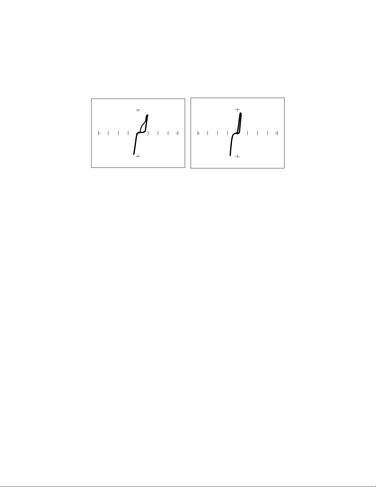
CMOS Components and Test Signal Frequency - F
S
CMOS logic circuits inherently have a significant amount of internal capacitance. This junction
capacitance is visible in the CMOS signatures when using the Tracker 2800. Capacitance in CMOS
circuitry may be emphasized or de-emphasized by changing the frequency of the test signal.
F
S
= 20 Hz F
S
= 400 Hz
Figure 5-8. Signatures of a 74HC14 Input Pin at Different Frequencies in 10V, 1K Range
Troubleshooting Digital Logic ICs
Comparison testing is a very powerful and effective test strategy when troubleshooting digital logic
using ASA. The Tracker 2800's Alt feature makes this technique quick and simple. Instead of having
to remember the specific signatures of a good component, all that's needed is to have a reference
component or board beside the one that's suspect. This section gave many examples of signatures from
TTL, Schottky TTL and CMOS logic families. Although from first inspection, these signatures appear
to be complex, remember that each of the ICs in the examples had really only four unique signatures
(buffer input, buffer output, power supply VCC and power supply ground). We can use this
characteristic to develop an effective model for troubleshooting digital logic chips.
1. Select the 50, 10V and 60 HZ range
2. Place or connect the black or blue ground clip lead from the Tracker 2800's Common jack to both
reference and suspect ICs or the board’s ground pin.
3. Place or clip the red test lead from the Tracker 2800's Channel A test terminal to the reference or
known good IC's pin. For this example, start with pin 1 of the known good IC.
4. Observe the signature. This is the signature of the pin of the known good component.
5. Keep the red probe on pin 1, an input pin. Probe all the other input pins of the suspect component
with the black probe until you have identified all the pins that have signatures that are the same as
pin 1.
6. Move the red probe on pin 2, an output pin. Probe all the other output pins of the suspect
component with the black probe until you have identified all the pins that have signatures that are
the same as pin 2.

80
REVIEW
Integrated circuits are complex devices that are built using basic electronic components.
The IC signatures resemble zener diodes.
There are many causes for IC failures and the Tracker 2800 can display its "health" as resistive
leakage, an open or a short.
Functionally identical pins on a single IC out-of-circuit will display the same signature.
The most common point for reference is ground, but V
CC
or another point might give a more
informative signature.
Different logic families exhibit different characteristic signatures.
Applications
Testing for faulty IC’s is one of the more common uses for the Tracker. A technician can compare IC’s
in or out of circuit.

81
5-2. ANALOG CIRCUITS
Analog components and circuits represent another family of integrated circuit components and include
operational amplifiers (op amps), comparators, references, regulators, timers and many other
specialized functions. These components and circuits present more troubleshooting challenges that are
unique to this particular family of ICs.
OP Amps
Frequently, each pin of an op amp creates a different signature on the Tracker 2800. This signature is
the result of the internal design of the chip and both the internal and external circuit elements
connected to it. This type of analog component typically has many internal junctions connected to each
pin and each pin may also be connected to numerous external components.
The following example will demonstrate ASA with a commonly used 741 type op amp. In this case it
is configured as an inverting amplifier circuit as in the schematic below.
Figure 5-9. Op Amp Symbol and Schematic Diagram of an Inverter Circuit.
We will examine the signatures of this analog IC and present some troubleshooting concepts for this
type of component.
OP Amp Signatures
Do the following to display the analog signatures of an op amp:
1. Select the 1K, 15V, 60Hz.
2. Place or clip the black test lead from the Tracker 2800's Common jack to the IC's ground or a
power supply pin. For this example, the negative power supply pin of the 741 is pin 4 and the
positive power supply is pin 8.
3. Use the red test lead from the Tracker 2800's Signal jack and probe each pin of the IC.
4. Observe that the signatures of each of the op amp's pins are unique.