Tracker-2800-2800S.pdf - 第67页
67 Diode 1N914 PNP 2N3906 NPN PN2222A Figure 4-20 . Signatures of a Diode and Collector-Base of Transistors at 1K and 15V. Notice that the collector- base signature of a NPN transistor is identical to the signature of …
66
Suggestions to minimize effects on bipolar transistors:
1. Use 5 Volts or less for testing the base-emitter or collector-emitter.
2. If using 8 Volts or greater, then keep the duration of the test as short
as possible.
3. Identify the base, emitter and collector pins of the device and then test
the collector-base junction to determine whether it is an NPN or PNP.
Since the emitter is not tested there will be no effect on h
FE
regardless of the selected voltage.
Bipolar Transistor Signatures
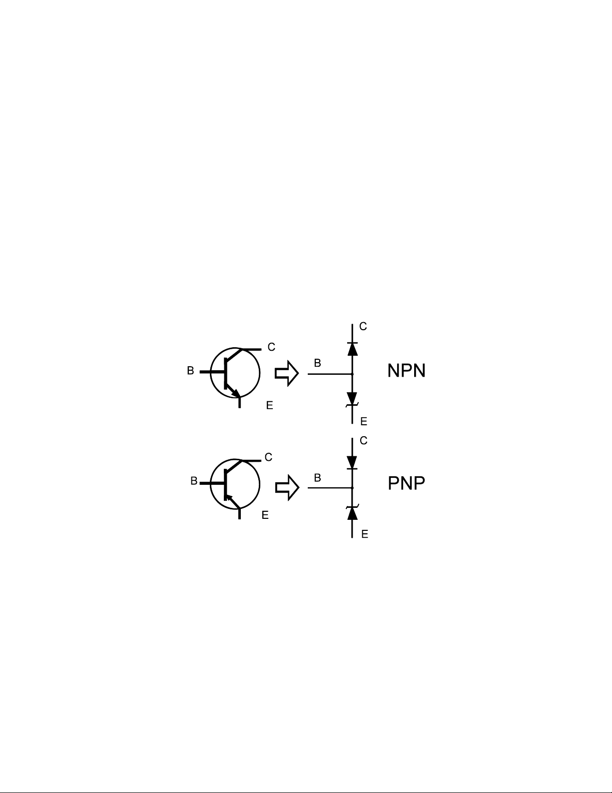
In order to better understand the signatures that transistors create on the Tracker 2800, we can model
these devices in terms of equivalent diode circuits. These are shown in figure 4-19. These figures show
that the collector-based junction analog signature looks similar to a diode signature, and the emitter-
base junction signature looks similar to a zener diode signature. Because we have already seen the
signatures of these two types of junctions when we tested diodes, they should be familiar to you.
Figure 4-19. NPN and PNP Bipolar Transistor Equivalent Circuits
Bipolar Transistor Base-Collector Signatures
Do the following to display the analog signatures of a bipolar transistor:
1. Select the 1K and 15V.
2. Place or clip the red test lead from the Tracker 2800's Channel A jack to collector lead of the
transistor.
3. Place or clip the black test lead from the Tracker 2800's Common jack to base lead of the
transistor.
67
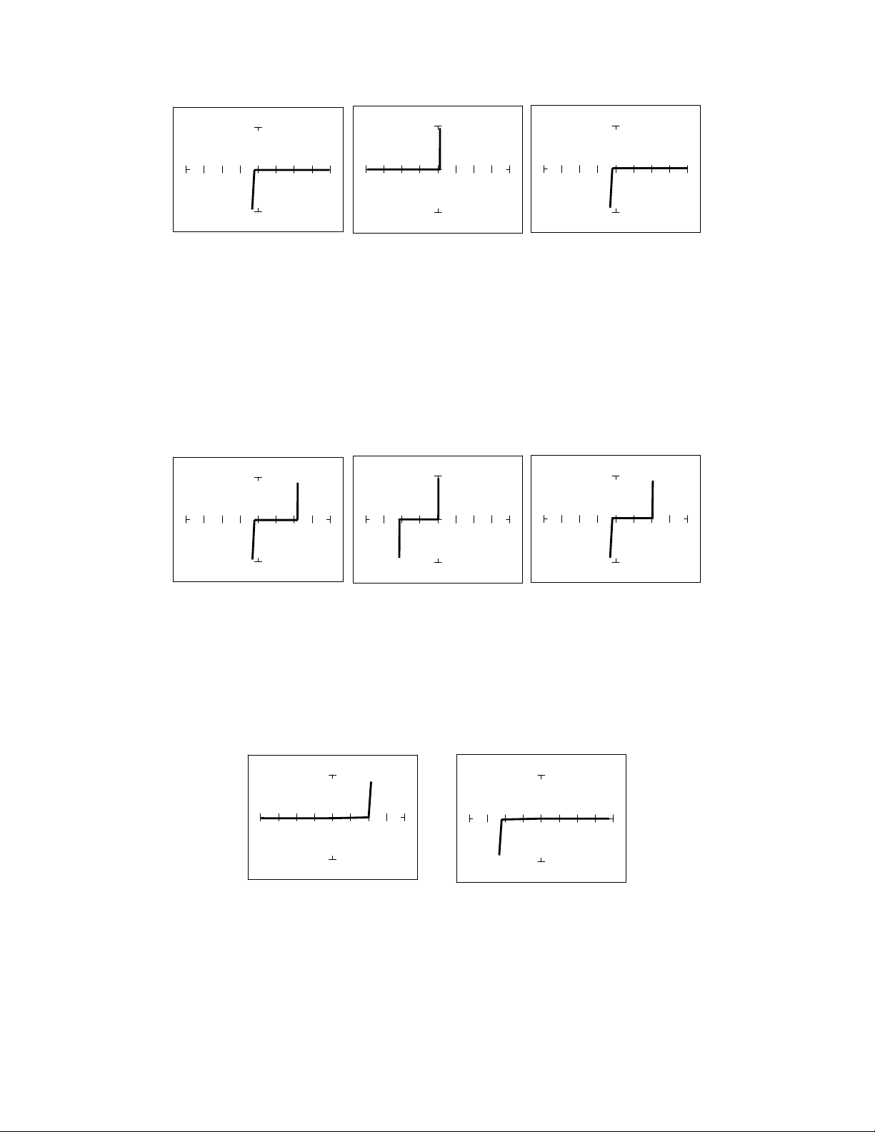
Diode 1N914 PNP 2N3906 NPN PN2222A
Figure 4-20. Signatures of a Diode and Collector-Base of Transistors at 1K and 15V.
Notice that the collector-base signature of a NPN transistor is identical to the signature of diode. The
collector-base signature of a PNP transistor, which has opposite polarity from a NPN, looks similar to
a diode with its polarity reversed. These are the signatures we expected from our circuit modeling. We
can do the same kind of comparison with the emitter-base circuits.
Zener Diode 1N5239B PNP 2N3906 NPN PN2222A
Figure 4-21. Signatures of a Diode and Emitter-Base of Transistors at 1K and 15V.
We can see that the base-emitter signature of the NPN transistor is nearly identical to the signature of
the zener diode. The emitter-base signature of a PNP transistor is also nearly identical but opposite in
polarity to the zener diode.
PNP Transistor - 2N3906 NPN Transistor - PN2222A
Figure 4-22. Signatures of the Collector-Emitter of Transistors at 1Kand 15V.
You can see that the collector-emitter signature of a PNP transistor looks like a forward biased diode
with the knee at approximately +7 Volts. The collector-emitter signature of a NPN transistor looks
similar to a reverse biased diode with the knee at approximately -7 Volts.
68
All bipolar junction transistors have essentially the same looking signatures.
Identifying Unknown Transistors
Sometimes, we need to identify unknown transistors. We may need to replace one in a circuit for
which we do not have a schematic. The Tracker 2800 makes this a relatively simple procedure because
each type of junction has a characteristic signature. This makes it possible to identify each of the
terminals and the polarity of the transistor.
Do the following:
1. Select 20V, 10Kand 60Hz.
2. Probe pin 1 with the red probe and pin 2 with the black probe.
3. Identify the signature.
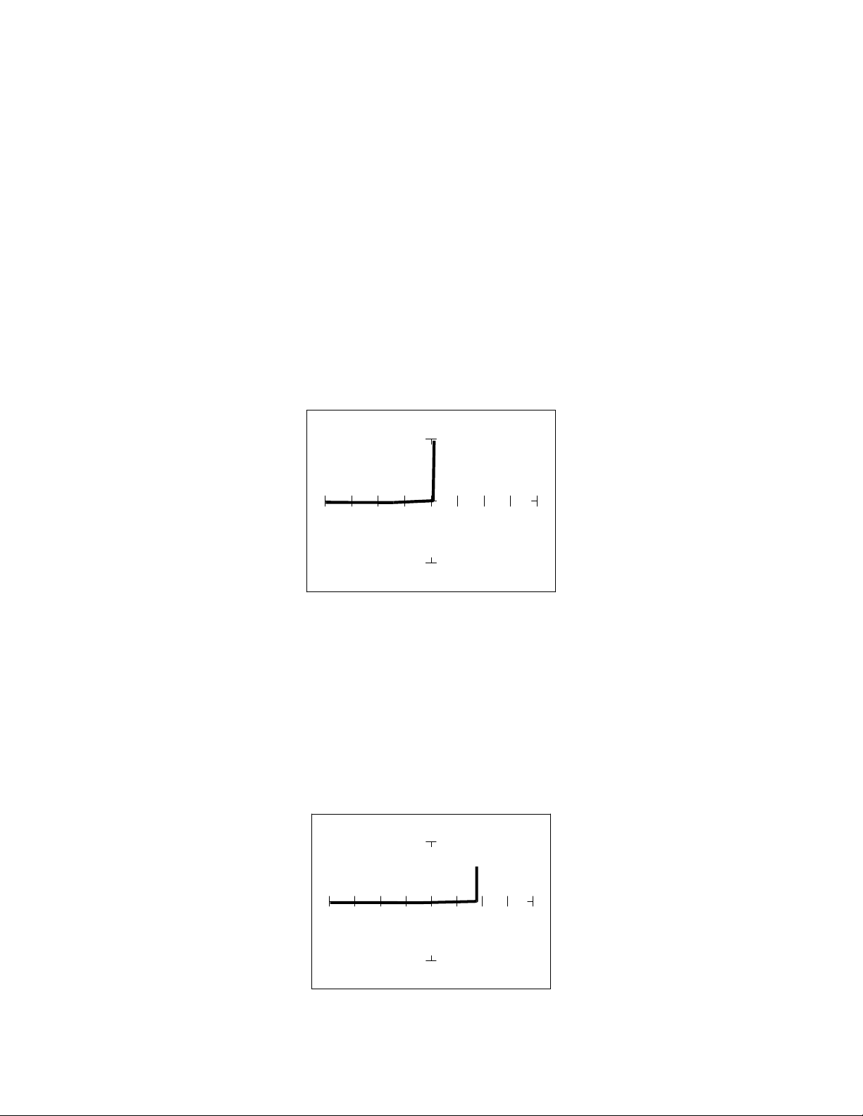
Figure 4-23. Signature of Pins 1 And 2 of an Unknown Transistor.
4. This looks like a collector-base signature. What you do not know yet, is which pin is the collector
and which pin is the base?
5. Probe pin 3 with the red probe and pin 2 with the black probe.
6. Identify the signature.
7. This looks like a collector-emitter signature.
Figure 4-24. Signature of Pins 3 and 2 of an Unknown Transistor.