Tracker-2800-2800S.pdf - 第22页
22 2-11 DC Voltage Source The built-in DC voltage source of the Tracker 2800 allows in-circuit testing of certain devices in thei r active mode. In addition to using th e red and black probes, the output of the DC voltag…
21
2-10 Smart Tracker Active Range (STAR) feature
The Tracker 2800 has a built-in operating feature called STAR (Smart Tracker Active Range). This
important feature protects sensitive components from possible exposure to excessive power (for
example, 15V and 10). The table 2-4 specifies the active and disabled voltage & resistance test range
combinations.
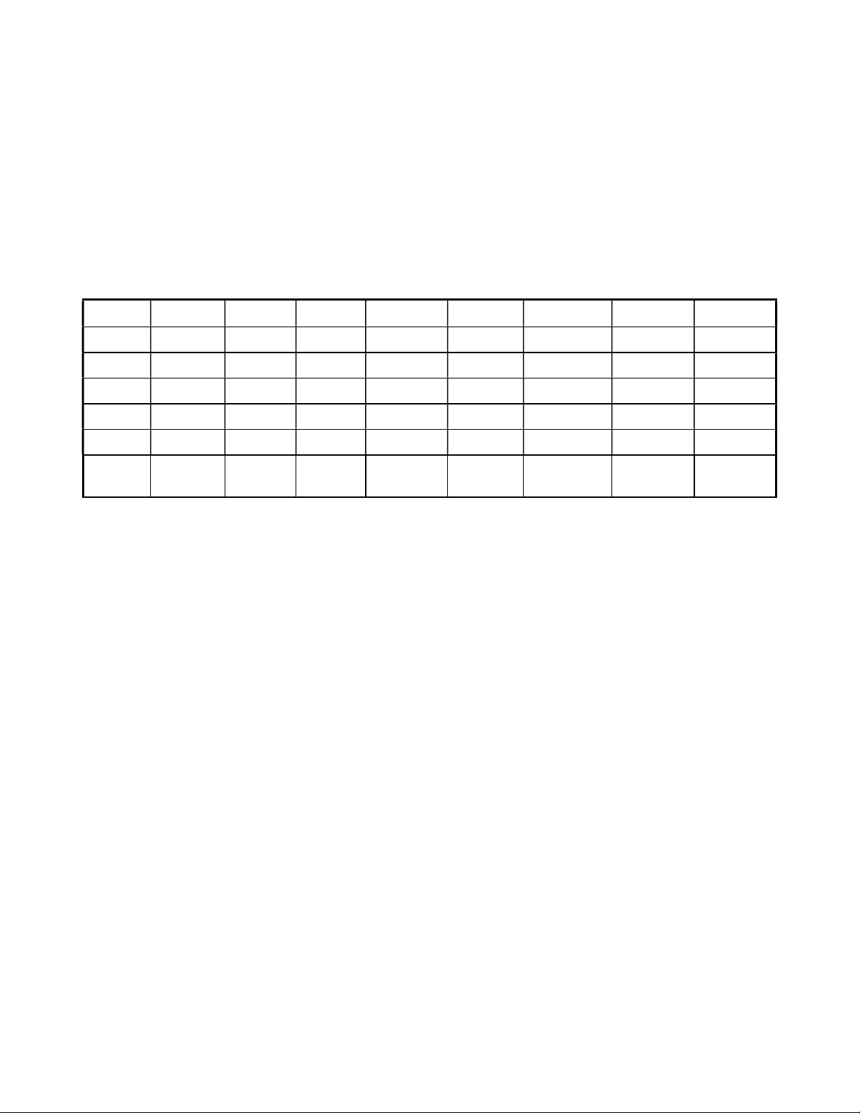
10 50 100 1k 5k 10k 50k 100k
200mV Enabled Enabled Enabled Enabled Enabled Enabled Enabled Enabled
3 V Disabled Enabled Enabled Enabled Enabled Enabled Enabled Enabled
5 V Disabled Enabled Enabled Enabled Enabled Enabled Enabled Enabled
10 V Disabled Enabled Enabled Enabled Enabled Enabled Enabled Enabled
15 V Disabled Disabled Disabled Enabled Enabled Enabled Enabled Enabled
20 V Disabled Disabled Disabled Disabled
Disabled Disabled
Enabled Enabled
Table 2-4. Valid Tracker 2800 Ranges (STAR)
To illustrate the STAR feature, do the following:
Select the 200mV, 10 range. This is a valid range shown by the LEDs being illuminated on the
200mV and 10 buttons.
Press the 5V button. Notice that the 5V LED is on and the resistance range changes to 50
automatically. The 5V at 10 range is disabled.
Now press the 15V button. Notice that the 1k resistance is automatically selected. The 15V at 50
range is disabled and the next valid resistance range was activated at the selected voltage.
22
2-11 DC Voltage Source
The built-in DC voltage source of the Tracker 2800 allows in-circuit testing of certain devices in their
active mode. In addition to using the red and black probes, the output of the DC voltage source is
connected to the control input of the device to be tested with the blue clip lead provided. The DC
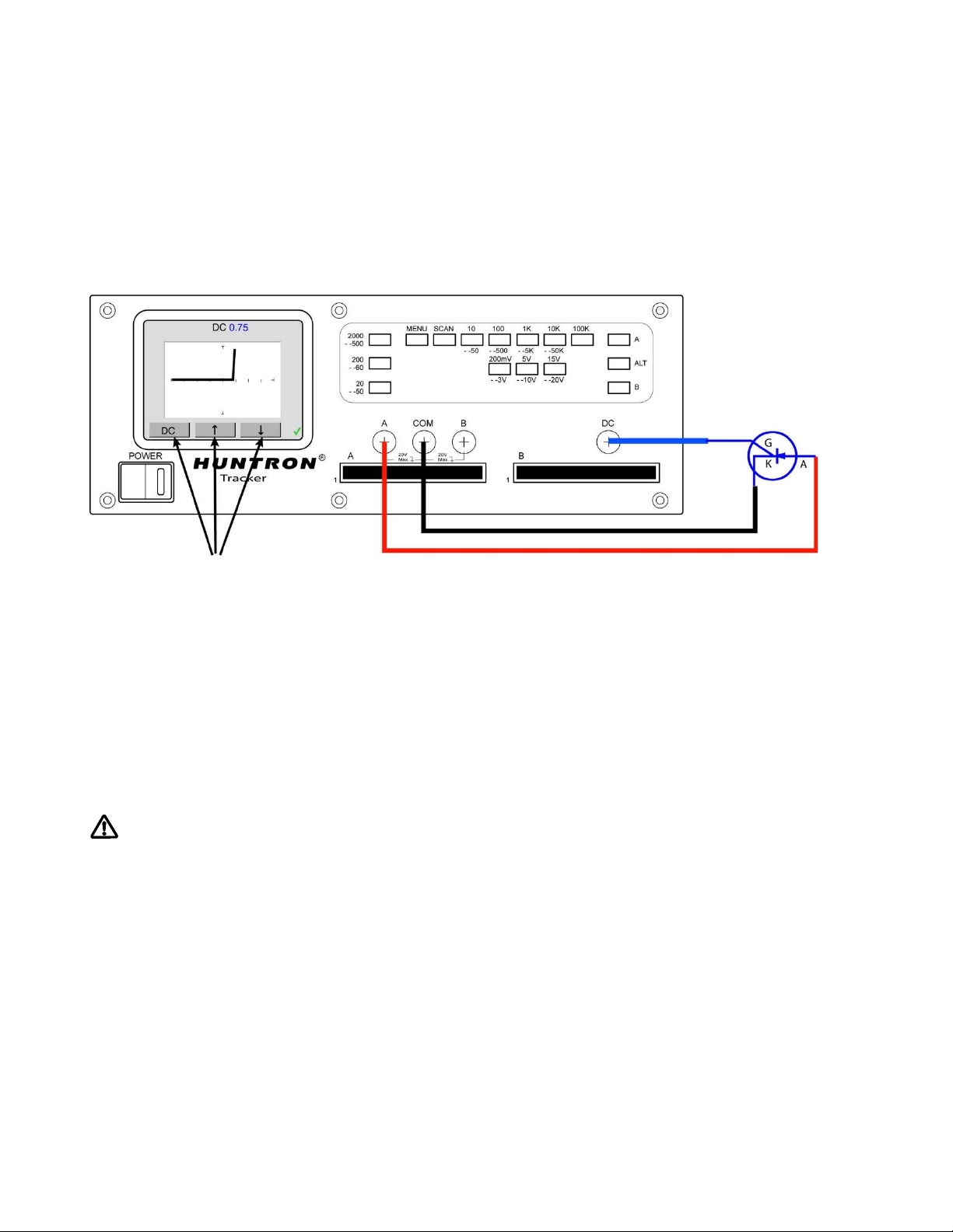
voltage source has one positive DC output. Figure 2-12 shows how to connect the Tracker to the
device under test (a SCR is used in this example) using the DC voltage source.
Figure 2-12. Tracker 2800 DC Source Typical Setup
The DC Voltage Source output is set using the DC Level controls (indicated by arrows) on the LCD
touch screen. While in the power-up menu, press the DC button then use the and arrow buttons to
increase or decrease the output voltage. The voltage level will be displayed at the top of the display.
The level control varies the magnitude of output amplitude from zero to + 10 volts. Press the DC
button to return to the power-up menu.
The DC Voltage Source can be used to test gated devices such as SCRs, TRIACS, optocouplers and
relays. It can also be used “bias test” transistors by applying voltage to the base while monitoring the
collector-emitter signature with the Tracker. This test method works similar to the basic functions of a
curve tracer.
CAUTION
The device to be tested must have all power turned off and all high voltage capacitors discharged
before connecting the Tracker to the device. Failure to do so may cause damage to the Tracker and
void the warranty.
DC Level
controls
23
2-12 Scanning with a Tracker 2800S
The Tracker 2800S is a scanning version of the Tracker 2800. It can automatically scan and compare
up to 40 pins using standard IDC connections on the front panel. Common uses for scanning include
connecting to PCB connectors and IC clips using custom ribbon cables.
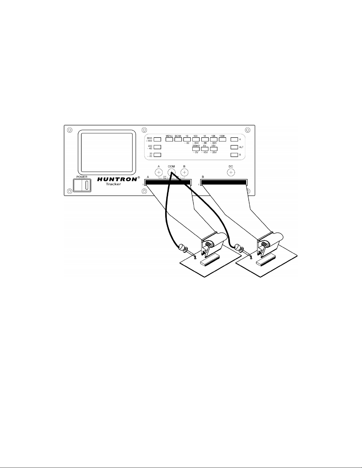
Figure 2-13 shows a typical Tracker 2800S configuration using standard DIP clips attached to through-
hole ICs.
Figure 2-13. Typical 2800S setup with DIP clips
Using the scanning capabilities of the Tracker 2800S is very easy. It is possible to scan using one
channel or both and also make signature comparisons between channel A and channel B.
To scan a component using the front panel cable interface, the package type and number of pins must
first be configured (the Tracker 2800S default configuration is a 16 pin DIP package). Using IC clips
and cables as an example, connect an IC cable and clip from each Tracker channel to ICs on side-by
side boards. Connect a Common lead to a common connection such as ground on each board.
Press the Menu front panel button to display the Main menu (first image in figure 2-14). Select SCAN
from the touch screen Main menu to display the SCAN menu (second image in figure 2-14). Select
PACKAGE from the SCAN menu to display the PACKAGE menu (third image in figure 2-14). Select
PACKAGE to display the PACKAGE select menu (middle right image in figure 2-14). Use the and
buttons to step up or down through the package choices of DIP, SIP, BOTH or FRONT. Press the
PACKAGE button to return to the Package menu. Press the PINS button to display the PIN select
menu (top right image in figure 2-14). Use the and buttons to increase or decrease the numbers of