Tracker-2800-2800S.pdf - 第40页
40 Review The signature of a purely resisti ve circuit is a straight line because the relati onship between volta ge and current in a purely resisti ve circuit is linear. This straight line signatu re can vary from …
39
The Effect of F
S
on Resistor Analog Signatures.
Select the 10V, 50 and 20Hz range. Change the Frequency to 60Hz, 1KHz and 2KHz. Observe the
resistor signatures in the following figures do not change as F
S
changes.
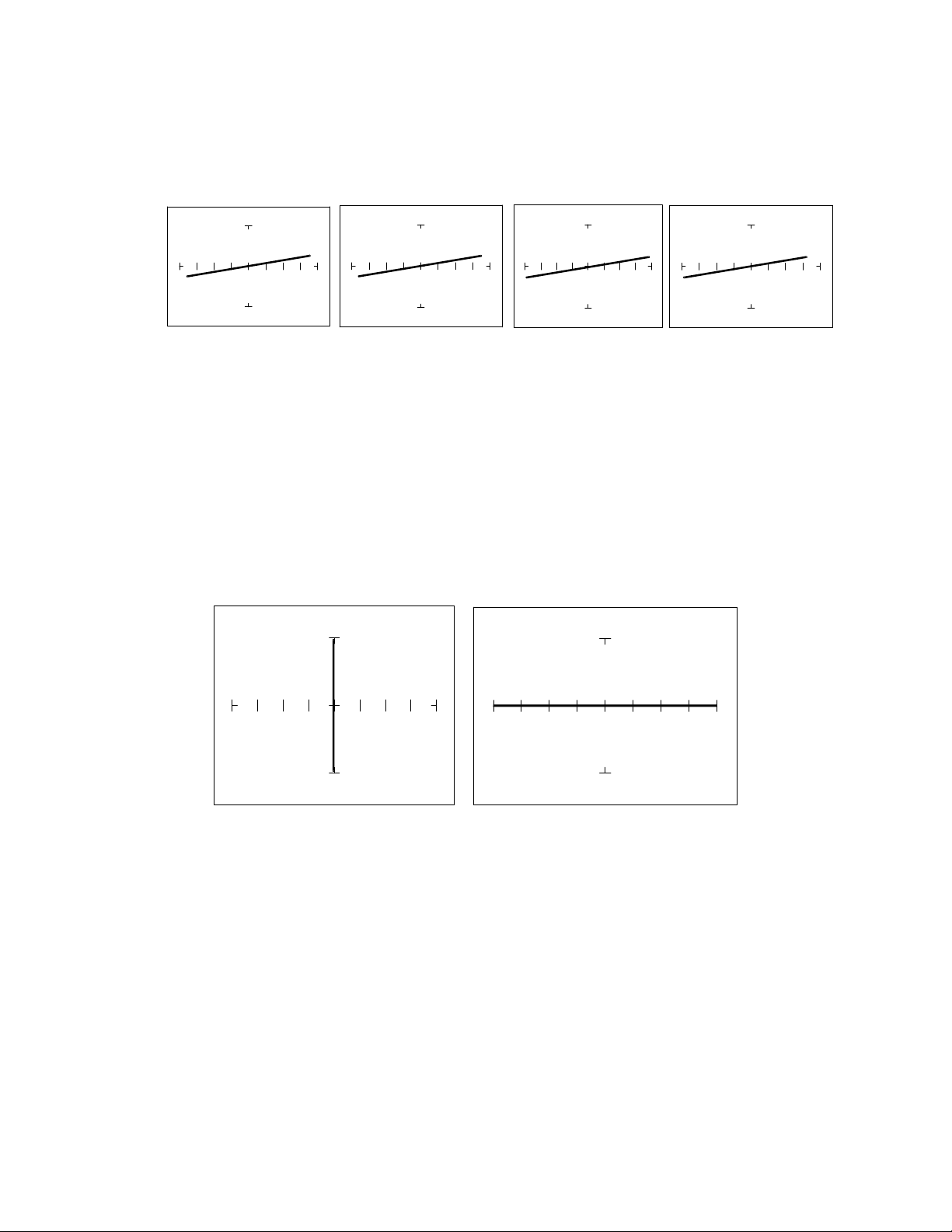
Fs = 20 Hz Fs = 60 Hz Fs = 1KHz Fs = 2KHz
Figure 3-5. Effect of Varying F
S
on a 100Resistor Signature.
Shorts, Opens and Resistor Faults
Two of the most common faults that occur in electronic components and circuits are shorts and opens.
A short circuit is typically a 0 to 10 low resistive path between two points in a component or
circuit that normally would have a higher resistance between them. An open circuit is a break between
two points in a component or circuit that prevents current from flowing.
Short Open
Figure 3-6. Short and Open Signature.

40
Review
The signature of a purely resistive circuit is a straight line because the relationship between voltage
and current in a purely resistive circuit is linear.
This straight line signature can vary from
completely horizontal (an open)
completely vertical ( a short)
As resistance increases
current decreases
the signature becomes more horizontal
As the range increases
the volts per division of the horizontal axis increases
the internal resistance increases
the signature becomes more vertical
Troubleshooting Applications
The Tracker 2800 is a fast and efficient continuity tester, providing real time information.
The Tracker 2800 will quickly locate resistor defects, shorts, opens and degradation that other
testers cannot find.
A majority of component failures are resistive in nature. This is important to remember; a
component fault may only appear in one range because of the resistive nature of the fault.
The Tracker 2800’s ability to determine the approximate fault resistance value greatly enhances the
troubleshooting capability if the correct value is known.
The Tracker 2800 can be used to adjust a potentiometer in circuit to an approximate operational
setting. This application requires a known good board. Adjust each potentiometer on the board
under repair to match the settings on a known good operational board. In most cases, the board
under repair can now be powered up to an operational state where it can be adjusted to true
specifications.
41
3-2. CAPACITORS
With a capacitor connected to the Tracker 2800, the test signal across it responds quite differently than
a resistor. The typical analog signature of a capacitor is an elliptical or circular pattern due to the fact
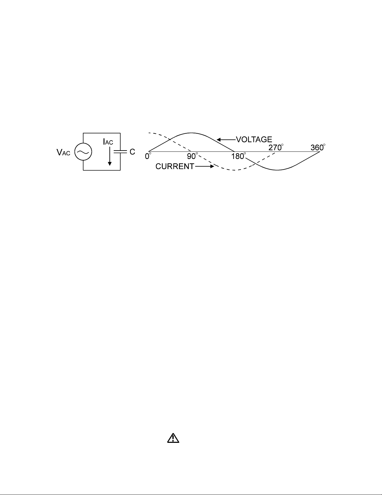
that relationship between the test signal's current and voltage are non-linear. The current's waveform is
90 degrees out of phase with respect to the voltage. The diagram below illustrates this basic principle
for capacitors.
Figure 3-7. Capacitor Circuit with Test Signal's Current and Voltage Waveforms.
As the test signal's voltage crosses zero volts and becomes more positive, the current flowing in the
circuit is at its maximum and becoming smaller. By the time the voltage has reached its maximum
value, the current in the circuit has ceased flowing. As the voltage begins decreasing toward zero, the
current begins increasing toward maximum. When the voltage reaches zero, the current is at its
maximum value. Similarly, this same pattern follows as the voltage goes negative.
Because the current is at its maximum value when the voltage is at zero, the current leads the voltage.
This is called phase shift and in a purely capacitive circuit, this phase shift equals 90. On the Tracker
2800, this analog signature appears as a circular waveform. The actual shape and slope of the elliptical
signature depends on the capacitance and impedance value of the component and the test signal's
voltage
,
internal resistance and frequency
.
Capacitor Analog Signatures
The goal of this part is to explore some capacitive signatures and to help you understand how capacitor
signatures are related to:
The capacitance (µf) of the circuit under test
The frequency (F
s
) of the test signal
The voltage (V
s
) of the test signal
The internal resistance (R
s
) of the Tracker 2800
Plug the red test microprobe in the Channel A jack, and the black test clip lead in the Common jack.
CAUTION