Tracker-2800-2800S.pdf - 第33页
33 Figure 2-28 Tracker 2800 Footswitch C ontrol Menus The footswitch controls work as follows: SCAN mode: Pressing th e footswitch will start and stop th e SCAN mode (same as manuall y pressing the front panel SCAN but…
32
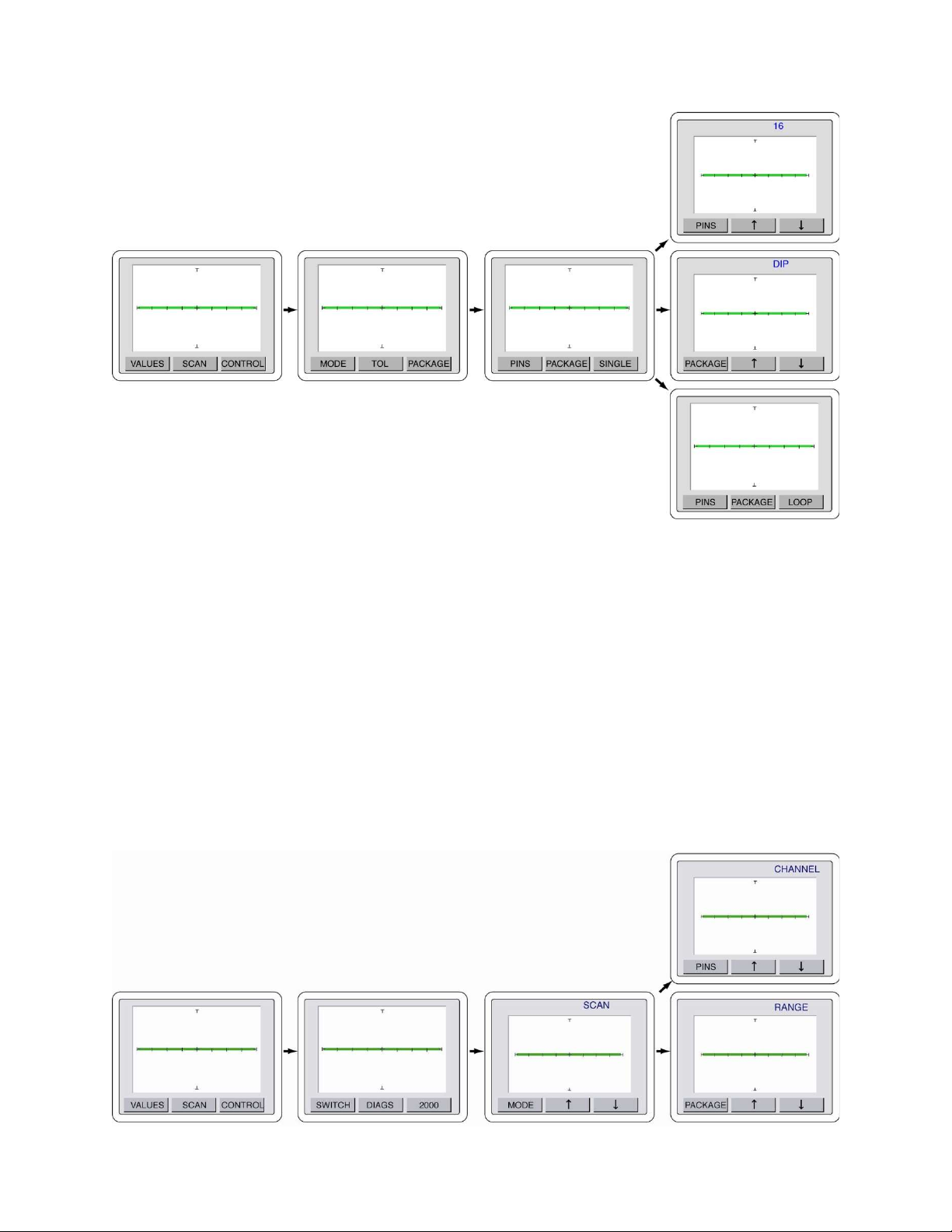
Figure 2-27. Scan/Package menus
Press the MENU front panel button three times to return to the power-up menu.
CONTROL – SWITCH Controls
The CONTROL – SWITCH menu controls the function of the optional footswitch when used with the
Tracker 2800.
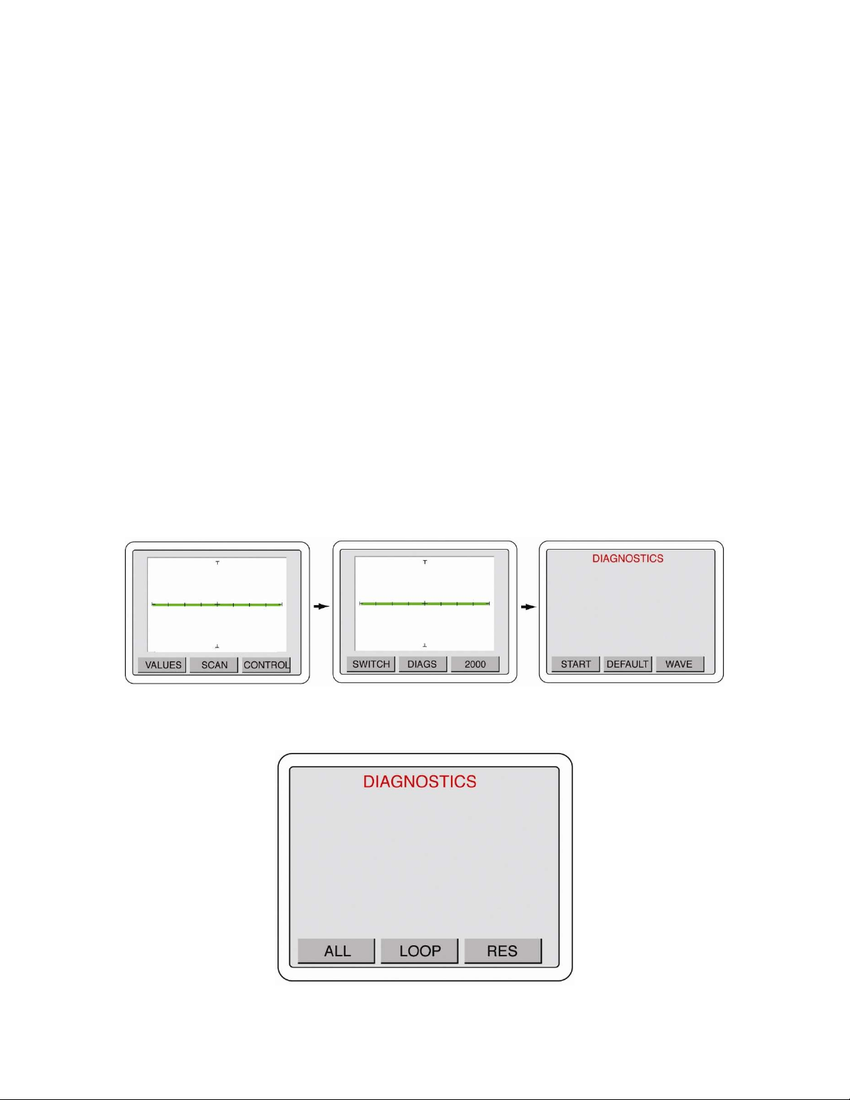
To configure the footswitch control press the front panel MENU button to display the Main menu on
the LCD (left image in figure 2-28). Press the CONTROL button on the LCD to display the Control
menu (image second from left in figure 2-28). Press the SWITCH button on the LCD to display the
Switch menu (image third from left in figure 2-28). Use the and arrow buttons to select the
footswitch control between SCAN (image third from left in figure 2-28), CHANNEL (middle image
on right in figure 2-28) and RANGE (bottom image on right in figure 2-28).
33
Figure 2-28 Tracker 2800 Footswitch Control Menus
The footswitch controls work as follows:
SCAN mode: Pressing the footswitch will start and stop the SCAN mode (same as manually
pressing the front panel SCAN button).
CHANNEL mode: Pressing the footswitch will change the channel from A to B or vice versa.
RANGE mode: Pressing the footswitch will change to the range set when the mode is selected
(i.e., set the range to 3V, 10K, 200Hz, select footswitch RANGE mode; pressing the
footswitch will automatically change the Tracker to this range). This is useful for changing to a
favorite range by simply pressing the footswitch.
Press the MODE button to return to the Control menu or press the front panel MENU three times to
return to the power-up menu.
CONTROL – DIAGS Controls
The Tracker 2800/2800S has built-in diagnostics to ensure that the unit is functioning properly. The
diagnostics can be accessed through the touch screen menus.
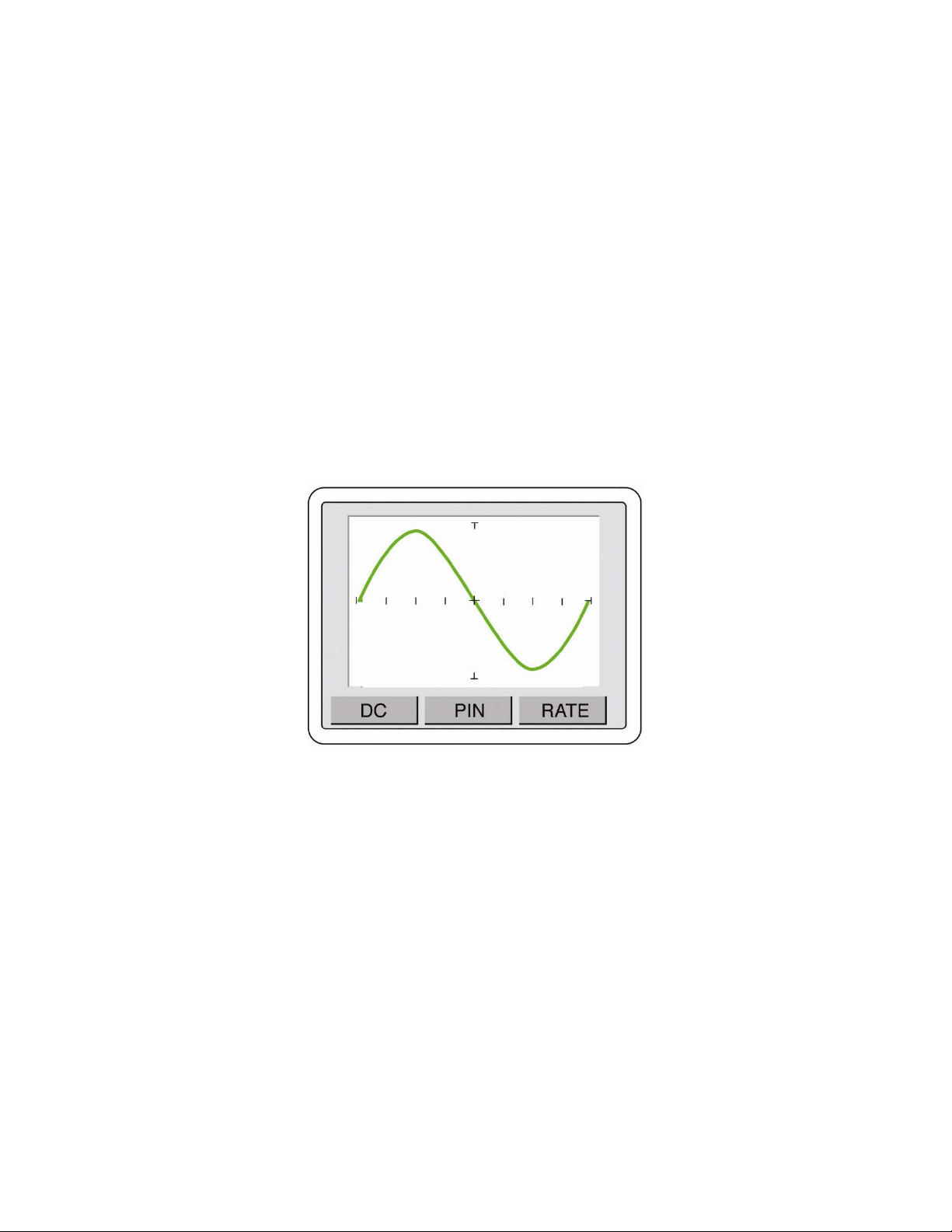
To access the diagnostics menus, press the MENU front panel button to display the Main menu. Press
the CONTROL button (left image in figure 2-29) to display the Control menu. Press the DIAGS
button (center image in figure 2-29) to display the Diagnostics menu (right image in figure 2-29).
Figure 2-29 Control – Diags menus
Press the START button to display a diagnostics selection menu (shown in figure 2-30).
Figure 2-30 Diagnostics selections
34
ALL: Executes all diagnostic routines
LOOP: Executes the loop compensation routine that will “zero out” added capacitance on the
test line from attached cables.
RES: Executes the resistor diagnostics. Tests the front panel resistance values with internal
reference resistors.
If any diagnostic routines fail, ensure that any cables attached to the front panel are removed and run
the diagnostics again. If failures continue to occur then contact Huntron Technical Support for
assistance.
In the Diagnostics menu, pressing DEFAULT will set the Tracker touch screen menus to the factory
default settings.
Pressing the WAVE button will change the Tracker to waveform display as shown in figure 2-31. This
button will change to SIG when waveform mode is enabled. Press SIG to return to signature mode.
Waveform mode is primarily useful when diagnosing problems with the Tracker.
Figure 2-31 Tracker waveform display