Tracker-2800-2800S.pdf - 第35页
35 CONTROL – 2000 M ode The Tracker 2800/2800S can be set to displa y three of the ranges used with t he popular Tracker 2000. To enable 2000 mode, press th e 2000 butto n in the Control menu. The displa y will change to…
34
ALL: Executes all diagnostic routines
LOOP: Executes the loop compensation routine that will “zero out” added capacitance on the
test line from attached cables.
RES: Executes the resistor diagnostics. Tests the front panel resistance values with internal
reference resistors.
If any diagnostic routines fail, ensure that any cables attached to the front panel are removed and run
the diagnostics again. If failures continue to occur then contact Huntron Technical Support for
assistance.
In the Diagnostics menu, pressing DEFAULT will set the Tracker touch screen menus to the factory
default settings.
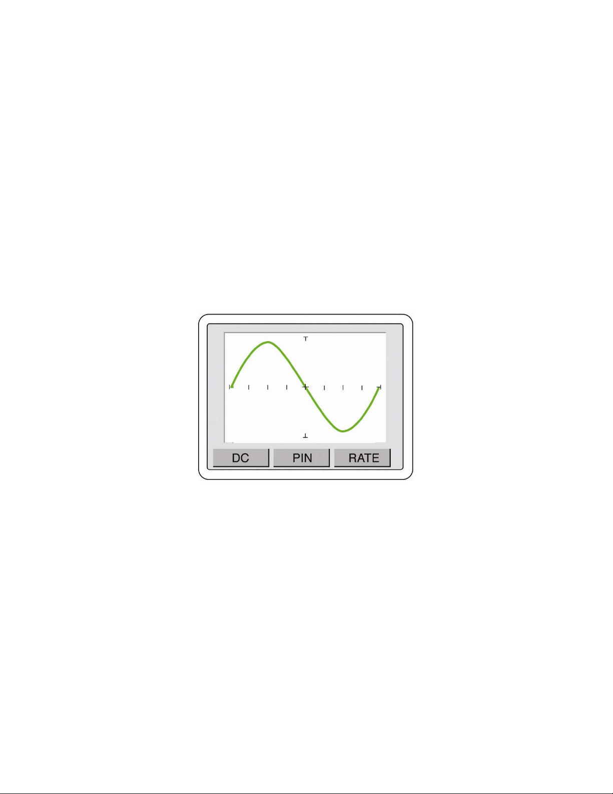
Pressing the WAVE button will change the Tracker to waveform display as shown in figure 2-31. This
button will change to SIG when waveform mode is enabled. Press SIG to return to signature mode.
Waveform mode is primarily useful when diagnosing problems with the Tracker.
Figure 2-31 Tracker waveform display
35
CONTROL – 2000 Mode
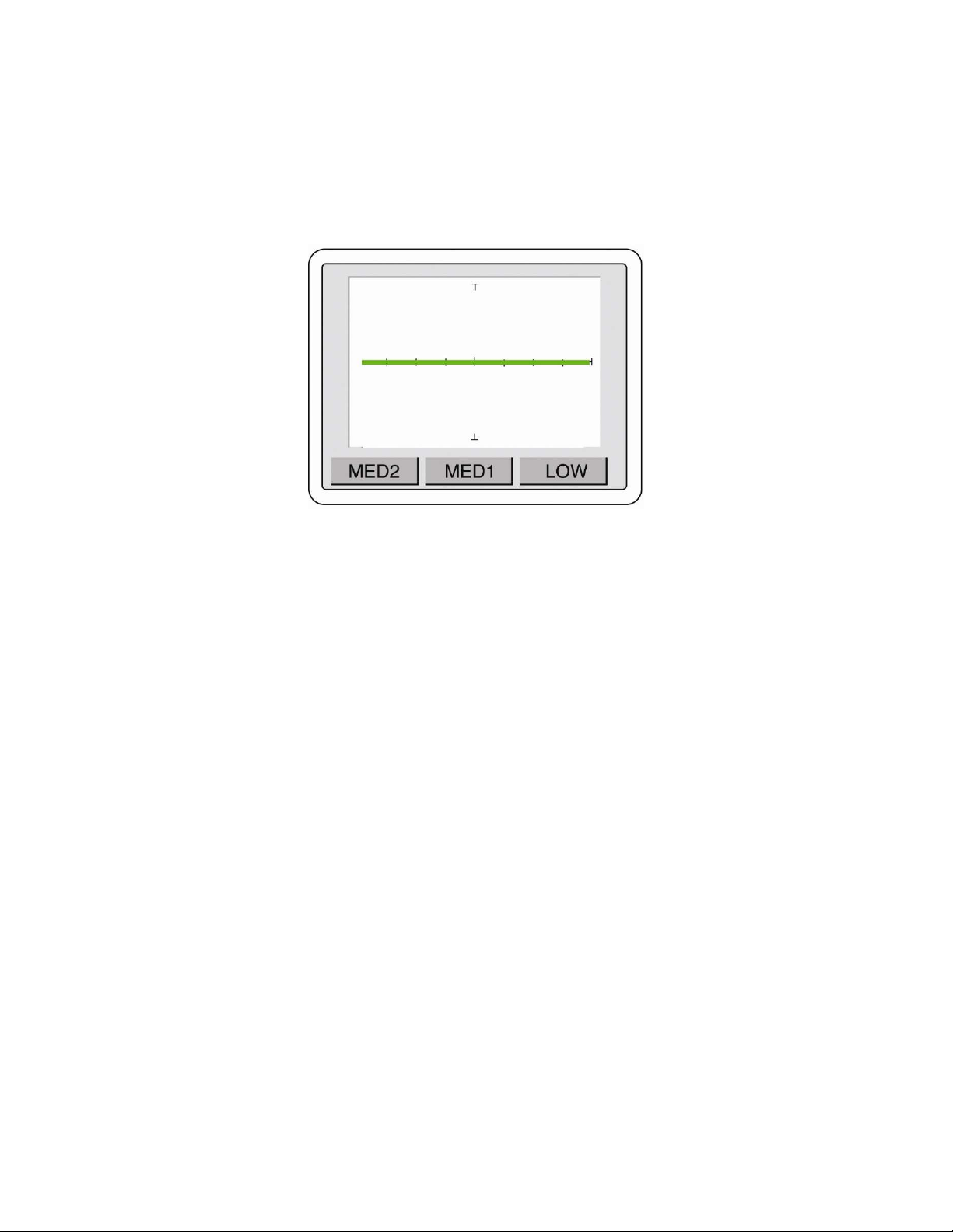
The Tracker 2800/2800S can be set to display three of the ranges used with the popular Tracker 2000.
To enable 2000 mode, press the 2000 button in the Control menu. The display will change to the
Tracker 2000 ranges as shown in figure 2-32.
Figure 2-32 Tracker 2000 mode
LOW range: 10V at 54
MED1 range: 15V at 1.2K
MED2 range: 20V at 26.7K
36
SECTION 3 TESTING PASSIVE COMPONENTS
3-1. RESISTORS
Exploring how the Tracker 2800 ranges interact with different resistance values is a good introduction
on how basic ASA troubleshooting is applied. This section will briefly familiarize you with Tracker
2800 basic operation and teach you how resistor signatures relate to both test range and the resistance
of the circuit under test. After completing this section, you will know how to:
Apply test probes across a resistor
Identify a pure resistive signature
Analyze and predict resistive signatures
As you go through the following section, make a mental note on the relationship between the Tracker
2800's test range parameters: voltage, resistance and frequency.
Put the red test lead in the Channel A jack, and the black test lead in the Common jack.
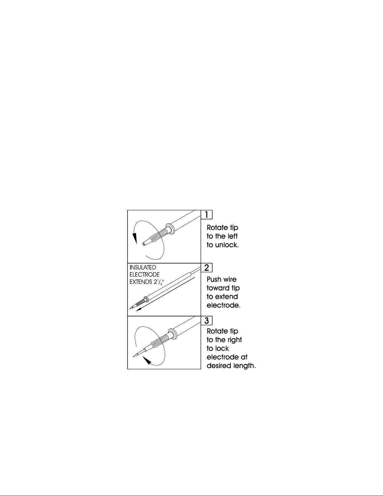
Micro Probe Adjustment (Do not over-tighten the tip in step 3):
Figure 3-1. Huntron MicroProbe Adjustment.