Tracker-2800-2800S.pdf - 第24页
24 pins to be scanned. Press the PINS button to return to the PACKAGE menu. Press the SIN GLE button to toggle (bottom right image in figure 2-14) betw een SINGLE (single pass t hen stop), LOOP (continuous scan) or STOP …
23
2-12 Scanning with a Tracker 2800S
The Tracker 2800S is a scanning version of the Tracker 2800. It can automatically scan and compare
up to 40 pins using standard IDC connections on the front panel. Common uses for scanning include
connecting to PCB connectors and IC clips using custom ribbon cables.
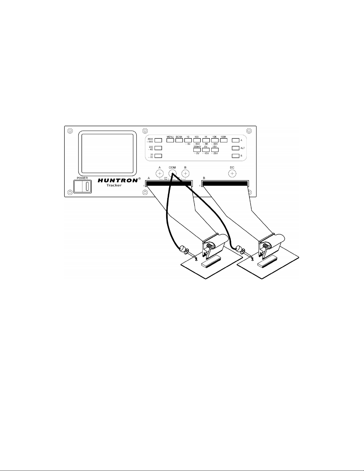
Figure 2-13 shows a typical Tracker 2800S configuration using standard DIP clips attached to through-
hole ICs.
Figure 2-13. Typical 2800S setup with DIP clips
Using the scanning capabilities of the Tracker 2800S is very easy. It is possible to scan using one
channel or both and also make signature comparisons between channel A and channel B.
To scan a component using the front panel cable interface, the package type and number of pins must
first be configured (the Tracker 2800S default configuration is a 16 pin DIP package). Using IC clips
and cables as an example, connect an IC cable and clip from each Tracker channel to ICs on side-by
side boards. Connect a Common lead to a common connection such as ground on each board.
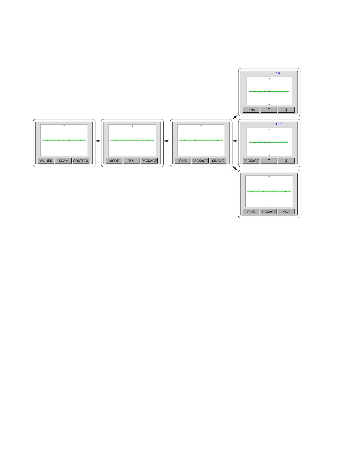
Press the Menu front panel button to display the Main menu (first image in figure 2-14). Select SCAN
from the touch screen Main menu to display the SCAN menu (second image in figure 2-14). Select
PACKAGE from the SCAN menu to display the PACKAGE menu (third image in figure 2-14). Select
PACKAGE to display the PACKAGE select menu (middle right image in figure 2-14). Use the and
buttons to step up or down through the package choices of DIP, SIP, BOTH or FRONT. Press the
PACKAGE button to return to the Package menu. Press the PINS button to display the PIN select
menu (top right image in figure 2-14). Use the and buttons to increase or decrease the numbers of
24
pins to be scanned. Press the PINS button to return to the PACKAGE menu. Press the SINGLE button
to toggle (bottom right image in figure 2-14) between SINGLE (single pass then stop), LOOP
(continuous scan) or STOP (stop on failure).
Figure 2-14. Scan/Package menus
Press the MENU button until the power-up menu is reached (the signature will become live). The pins
can be manually scanned by pressing the PIN button on the LCD. Make sure you have a Common
connection to the PCBs being tested otherwise you will see only open circuit signatures (horizontal
lines) on the Tracker display. The display will change to show the current pin number at the top. Press
the and arrow buttons to step manually through the pins on the connected device with the
signature for each pin will be displayed on the LCD. Press A to view only channel A, B to view only
channel B or press the ALT button to view signatures on channel A and channel B. Comparison of the
A (green signature) and B (red signature) channels is automatic when the Tracker is in ALT mode.
Note the green “check” or red “X” mark on the bottom right portion of the LCD will indicate a passed
or failed comparison.
To scan without having to increment the and arrow buttons on the PIN menu, press the front panel
SCAN button and the 2800S will step through the pins automatically. Press the SCAN button again to
stop the scanning. By default, selecting the SCAN button will test each pin in each 2800S resistance
range before stepping to the next pin. To change which range parameter is scanned, press the front
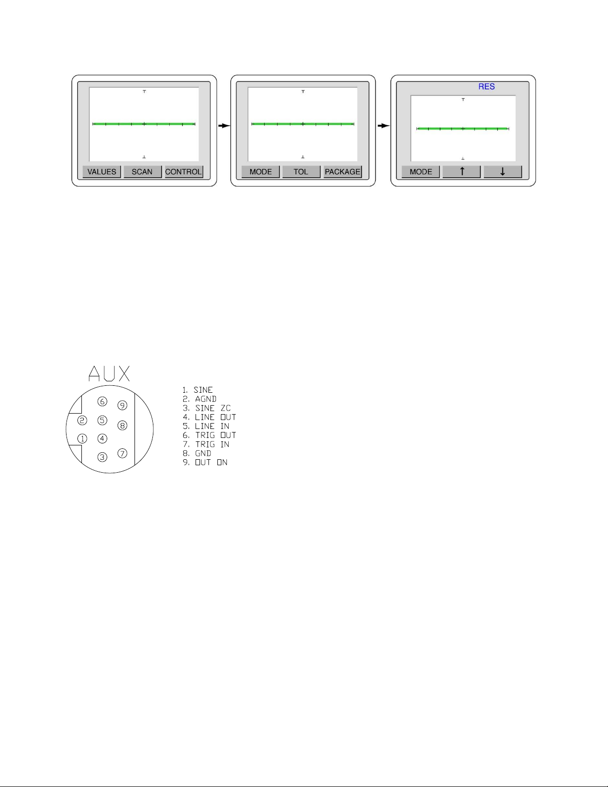
panel MENU button to display the Main menu (left image in figure 2-15) on the LCD. Press the
SCAN button on the LCD to display the SCAN menu (middle image in figure 2-15) and press the
MODE button on the LCD to display the MODE menu (right image in figure 2-15). Use the and
arrow buttons to change the scan mode between resistance (RES), frequency (FREQ), none (NONE)
and voltage (VOLT).
Press SCAN Press PACKAGE Configure Package
25
Figure 2-15. Selecting range parameter used while scanning
Press the MENU button until the power-up menu is reach (the signature will become live at this point).
Pressing the SCAN button will now scan through the component pins using the range parameter
selected in the Scan MODE menu.
2-13 Auxiliary (AUX) connector description
The rear panel Auxiliary (AUX) 9 pin Din connector pins are shown figure 2-16. This connection is
used for control of the Tracker with the optional footswitch accessory.
Press the SCAN button Press the MODE button Use and to select the Scan mode
Figure 2-16
Auxiliary connector pin out
diagram