Tracker-2800-2800S.pdf - 第52页
52 disconnected from AC power. Then connect the red and black t est probes across the prongs on th e AC line cord going to the computer. Turn the compute r power switch to the On position. If there is a response on the T…

51
Since inductors in reality are not pure inductors, the elliptical signatures they form on the Tracker 2800
display usually is distorted. Inductors constructed with a ferrite core makes the inductive
characteristics different from those constructed without. The Tracker 2800 responds with a unique
analog signature for each inductor type.
R
S
F
S
=
20 Hz. F
S
= 2 kHz
100 k
100H – 1000H 50mH – 1000mH
10
1H – 100H 1uH – 10mH
Table 3-2. Tracker 2800 Minimum and Maximum Inductor Values.
REVIEW
Inductors display elliptical signatures similar to capacitors. Since the inductor also exhibits
resistance, due to its construction, the ellipse may be distorted.
As the Tracker 2800 test signal’s frequency is increased, the ellipse signature becomes flatter. This
response is opposite to that of a capacitor.
As the Tracker 2800 internal resistance R
S
increases, an inductor's signature becomes more vertical
(like the capacitor signature).
When an inductor has a ferrite core, its signature distorts from a non-ferrite inductor’s ellipse.
APPLICATIONS
The Tracker 2800 is excellent for troubleshooting inductors. It can reveal shorted or open windings
in large variety of inductive components.
Components that are inductors or have inductive characteristics can be found in many real world
applications. For example, some of these are power transformers, relays, solenoids, flybacks,
speakers, magnetic sensors, stepping motors and motor windings.
The best technique for testing inductors is the comparison of a known good component's signature
to a suspect component. For example, a motor armature has typically numerous windings so every
winding should have a similar analog signature. This fact is true whether it's from an elevator or a
tape deck. The armature of a DC motor can be tested by simply connecting to the motor brush
leads and then adjusting the test range for the most pronounced or descriptive signature. Slowly
turn the armature. Observe the Tracker 2800’s signature display. This test will check continuity,
the inductance, and the condition of each brush contact without disassembling the motor.
A computer switching power supply contains inductors. For example, a computer is reported
“dead." To make a quick diagnosis of the possible problem first make sure the computer is

52
disconnected from AC power. Then connect the red and black test probes across the prongs on the
AC line cord going to the computer. Turn the computer power switch to the On position. If there is
a response on the Tracker 2800 signature display, adjust the test range for the most pronounced
inductive signature. Flick the power switch off and on and watch for noisy switch contacts. If there
is no response, start by checking each component up to the primary winding of the transformer.
With this technique, we have just verified the AC cord, the AC noise filter, the fuse, the power
switch and the primary winding of the transformer, without removing the cover from the computer.
Another simple test for a speaker or microphone is to apply the Tracker 2800 signal in V
S
= 10 V,
R
S
= 50 , F
S
= 60Hz range to the device input leads and listen for the 60 Hz tone or audible hum.
To test solenoids, connect the test probes to the coil leads and manually move the plunger or
activator in and out while observing if its signature changes.
53
3-4. ELECTROMECHANICAL SWITCHING COMPONENTS
Switches are electrical devices that either stop or allow current to flow in a circuit. They are either in
an on or off state. Switching devices come in all types and sizes. There are simple mechanical
switches, relays, optical switches, and many kinds of semiconductor switches. They are different
because each uses a different kind of stimulus to turn them on or off. Because there are so many kinds
of switching devices, there is no single testing procedure that will test them all completely. With the
Tracker 2800, the test signal can be setup so that the switch's analog signature will verify its switching
function. The goal of this section is to develop a test strategy using ASA to test the switching function.
This is not a complete test, but it will be enough to determine whether or not the device is functioning
as a switch.
Manually Operated Mechanical Switches
A mechanical switch has two states: it is either open or closed. When open, no current can flow; when
closed, it acts as a short and allows current to flow. The Tracker 2800 can test the switching function
of mechanically activated switches easily. Unlike the DVM that samples and gives a continuity
measurement, the Tracker 2800 displays real time activity so if a switch has noisy, resistive or
intermittent operation, its analog signature on Tracker 2800's display will reflect these conditions.
Plug the red test microprobe in the Channel A jack, and the black test clip lead in the Common jack.
Do the following to display the analog signature of a mechanical switch:
1. Select the V
S
= 10 V, R
S
= 50, F
S
= 60Hz range button.
2. Place or clip each test lead to the switch leads and observe its signature on the Tracker 2800
signature display.
3. Turn the switch to it’s on or off position.
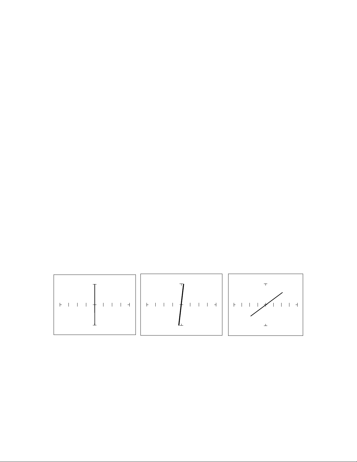
10K 1K 50
Figure 3-23. Signatures of a pressed Keyboard Pushbutton Conductive Elastomer Switch.
Note that as the ranges change from 10Kto1Kto 50, the signature tilts away from the vertical.
This characteristic is similar to other components with internal resistance.