Tracker-2800-2800S.pdf - 第64页
64 Applying What We have Learned Diode damage or degrad ation can appear as a loss of sharpness or roundin g in the “knee”. While fault y diodes display resistive current and volta ge legs, they are usuall y nonlinea…
63
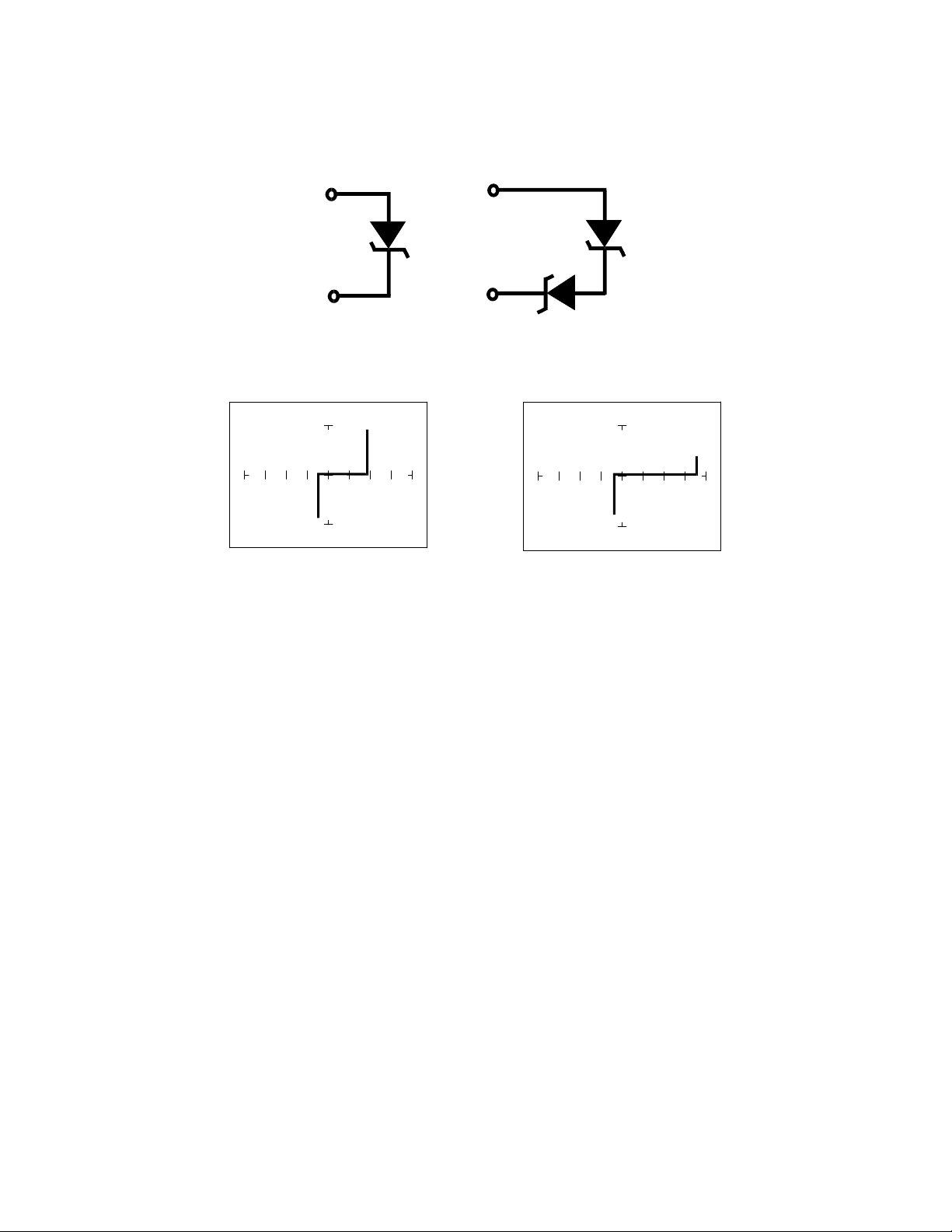
Figure 4-15. Tracker 2800 Core Circuit Block Diagram with a Zener Diode.
Figure 4-16. Single Zener Diode and two Zener Diodes in Series.
Single 1N5239B Zener Diode 2 Zener Diodes in Series, 1N5239B
Figure 4-17. Signatures of A Zener Diodes at 20V, 10K
Since each horizontal division on the Signature graticule (in 20V range) is approximately 5 Volts, from
the signature on the left you can estimate that this is about a 9 volt zener diode. The signature at the
right is the signature of two zener diodes connected in series. The Zener voltage (V
Z
) of this circuit is
the sum V
Z
of each of the separate diodes. The signature shows this voltage to be approximately 18
Volts.
Review
Diodes conduct current in one direction (forward biased) and not the other. The diode's analog
signature displays this characteristic as the “knee” effect or pattern.
Diodes have polarity, an anode and a cathode.
Diode defects, other than opens and shorts, are usually resistive.
A diode in series or parallel with a resistor or capacitor will create a composite signature displaying
both characteristics. The Tracker 2800 makes it easier to separate these characteristics from
composite signatures using the three parameters F
S
, R
S
and V
S
.
Zener diodes are special diodes that conduct when reverse biased at a specific voltage.

64
Applying What We have Learned
Diode damage or degradation can appear as a loss of sharpness or rounding in the “knee”.
While faulty diodes display resistive current and voltage legs, they are usually nonlinear or curved.
The polarity of an unmarked diode can be determined by the orientation of the display with a
known diode.
The Tracker 2800 can be used to identify an unknown zener diode. If the zener diode is damaged,
locate a good one, possibly on another board or in the same circuit and use the Tracker 2800 to
approximate the voltage.
Look for the zener effect when checking voltage regulators such as the 7805 type. This can help
determine an unknown or faulty device.
The Tracker 2800 can be used to test and determine the four pin connections on a bridge rectifier,
(AC1, AC2, + and -).
65
4-2. TRANSISTORS
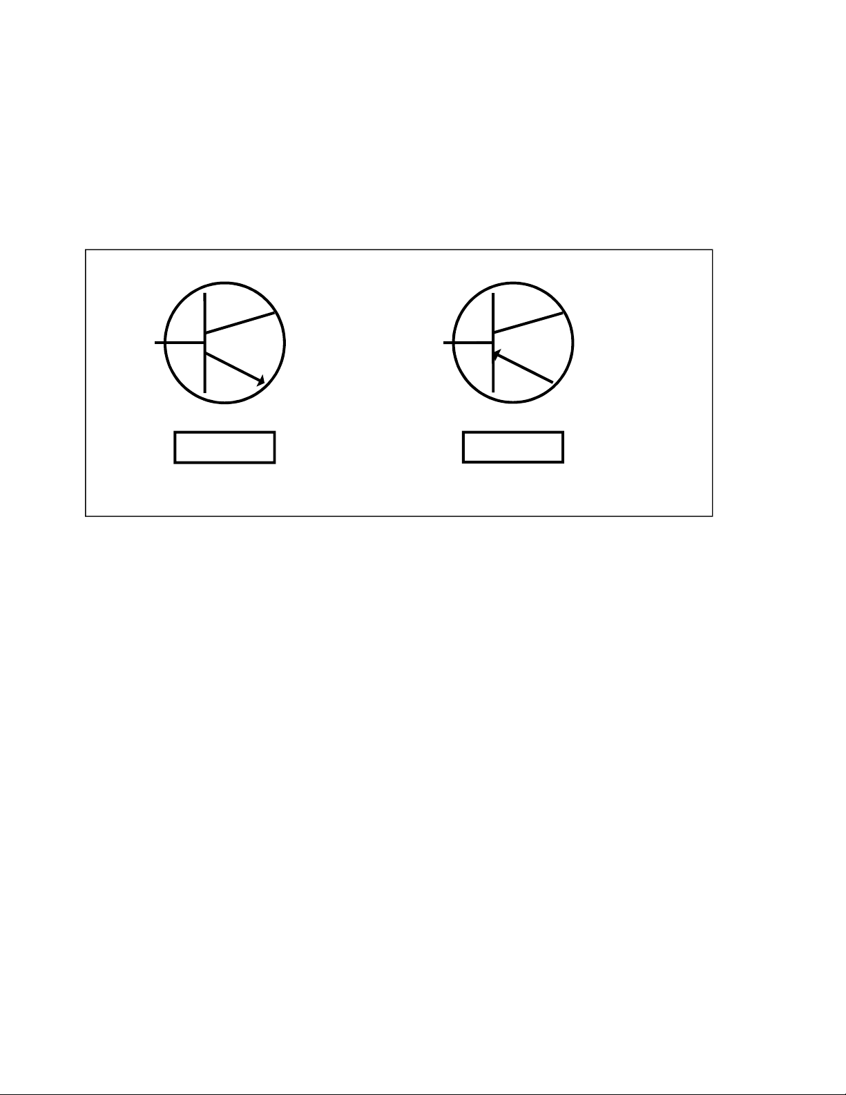
A bipolar transistor is a three layer device. There are two basic types. A PNP transistor has a layer of
n-type silicon material sandwiched between two layers of p-type material. An NPN transistor has a
layer of p-type silicon material sandwiched between two layers of n-type material. Figure 4-18 shows
the relationship between type of material and circuit symbol for a PNP and an NPN transistor.
Figure 4-18. Diagram of an NPN and PNP Bipolar Transistor.
IMPORTANT NOTE
Use of this instrument may alter the current gain (h
FE
or ß) of a bipolar transistor whenever the emitter
is tested. Either the base-emitter or collector-emitter test circuits satisfy this criterion. While heating of
the device due to the current produced by the instrument may cause a temporary change in h
FE
(most
noticeable in the low range), a permanent shift in h
FE
may occur whenever the base-emitter junction is
forced into reverse breakdown (~8-20 Volts). If the voltage is above 8 Volts, then the magnitude of the
shift depends on the duration of the test and the resistance selected. Reducing the voltage to 5 Volts or
less will avoid this problem.
Most bipolar transistor circuit designers take into account a wide variation in h
FE
as a normal
occurrence and design the related circuitry to function properly over the expected range of h
FE
. The
effects mentioned above are for the most part much smaller than the normal device variation so that the
use of this instrument will have no effect on the functionality of good devices and can fulfill its
intended purpose of a means to locate faulty components. However, some circuits may depend on the
h
FE
of the particular part in use, e.g. instrumentation that is calibrated to certain h
FE
value, or precision
differential amplifiers with matched transistors. In such instances, this instrument should not be used
on the base-emitter junction as it may cause the h
FE
to shift outside the limited range where calibration
can correct for any change.
PNP
NPN
E
E
B
B
C
NPN PNP
BASE
COLLECTOR
EMITTER
BASE
EMITTER
C
COLLECTOR