00197004-04_UM_X-Serie-S_EN.pdf - 第105页
User manual SIPLACE X-Series 2 Operational safety From software version 706.1 SP1 Version 10/2014 2.10 Lock out and tag out procedure 105 2.10 Lock out and t ag out procedure 2.10.1 Purpose and scope Before performing an…
2 Operational safety User manual SIPLACE X-Series
2.9 Energy state of the machine after switching off at the main power switch From software version 706.1 SP1 Version 10/2014
104
2
2.9.2 Machine switched off at the main power switch and disconnected
The machine is unpowered, apart from slight residual voltages in the power supply unit.
2.9.3 Compressed air conditions in the machine after switching off at the main
power switch
When you switch off the main switch (item 1 in fig. 2.9 - 1, page 101) or if the power supply to the
machine fails, the electrically controlled main valve of the compressed air unit (item 1 in fig. 2.8 -
1, page 100 ). The pressure will drop to 0 MPa (0 bar) within 5 seconds.
Module Voltage
Terminal panel X100
terminals L1, L2, L3
3 x 200 V~
3 x 208 V~
3 x 220 V~
3 x 230 V~
3 x 380 V~
3 x 400 V~
3 x 415 V~
Service socket X102
115 V~
120 V~
130 V~
156 V~
220 V~
230 V~
240 V~
Automatic circuit breaker F1
115 VAC
120 VAC
130 VAC
220 VAC
230 VAC
240 VAC
Main switch Q1
Terminals L1, L2, L3
3 x 200 VAC
3 x 208 VAC
3 x 230 VAC
3 x 380 VAC
3 x 400 VAC
3 x 415 VAC
Main switch Q1
terminals to transformer unit T1, T2, T3 0 VAC
Power supply unit
(see Residual voltages and discharge times after switching off the main switch
, page 97)

User manual SIPLACE X-Series 2 Operational safety
From software version 706.1 SP1 Version 10/2014 2.10 Lock out and tag out procedure
105
2.10 Lock out and tag out procedure
2.10.1 Purpose and scope
Before performing any preventive maintenance work or service work, a procedure of locking and
tagging must be followed. The procedure, when followed correctly eliminates the possibility of an
employee being injured.
2
2.10.2 Description
Whenever it becomes necessary to isolate, control and release energy, the following procedure is
to be followed
Notify affected employees.
Shut down the equipment. Carry out all normal stopping procedures:
– Press the stop button.
– Shut down the control computer.
– Switch the machine off at the main power switch.
Isolate the machine from all its energy sources:
– Shut off the compressed air supply
– Shut off the main power supply
Lock out the machine.
– Attach a lock whenever possible (e.g. to the motor contactor).
PLEASE NOTE
Minimum requirements
These procedures represent the minimum lock/tag out requirements for the preventive
maintenance or service work. Any additional safeguards needed to complete work safely
can be specified by facilities supervision, the safety officer, the safety committee and the
health department.
2 Operational safety User manual SIPLACE X-Series
2.10 Lock out and tag out procedure From software version 706.1 SP1 Version 10/2014
106
2
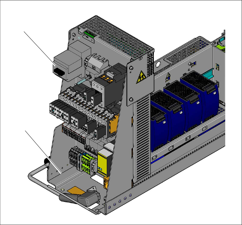
Fig. 2.10 - 1 Position of the motor contactor
2
(1) Power supply
(2) Motor contactor with main switch function ("main power disconnection feature")
Alternatively: tag out procedure
If a machine can be locked out, it must be. However, there are situations where energy iso-
lating devices cannot accommodate locks. In these cases, the energy isolating devices must
be tagged to warn employees that the machine is de-energized for servicing. The tag must
be securely fastened, it must be placed in a position visible to all and it may only be removed
by the person who attached it. 2
(2)
(1)