00197004-04_UM_X-Serie-S_EN.pdf - 第236页
4 Setting up and commissioning User manual SIPLACE X-Series 4.2 Infrastructure at the installation location From software ve rsion 706.1 SP1 Version 10/2014 236 4.2.3.5 Connecting the power supply cable 4 Fig. 4.2 - 5 T …
User manual SIPLACE X-Series 4 Setting up and commissioning
From software version 706.1 SP1 Version 10/2014 4.2 Infrastructure at the installation location
235
4.2.3.4 Mains connection - delivery configuration
The main power connection is configured according to the power supply of the country concerned.
– The machine is configured for voltages of 200V AC, 220V AC or 230V AC.
The machine has a mains power cable WITHOUT plug. 4
4
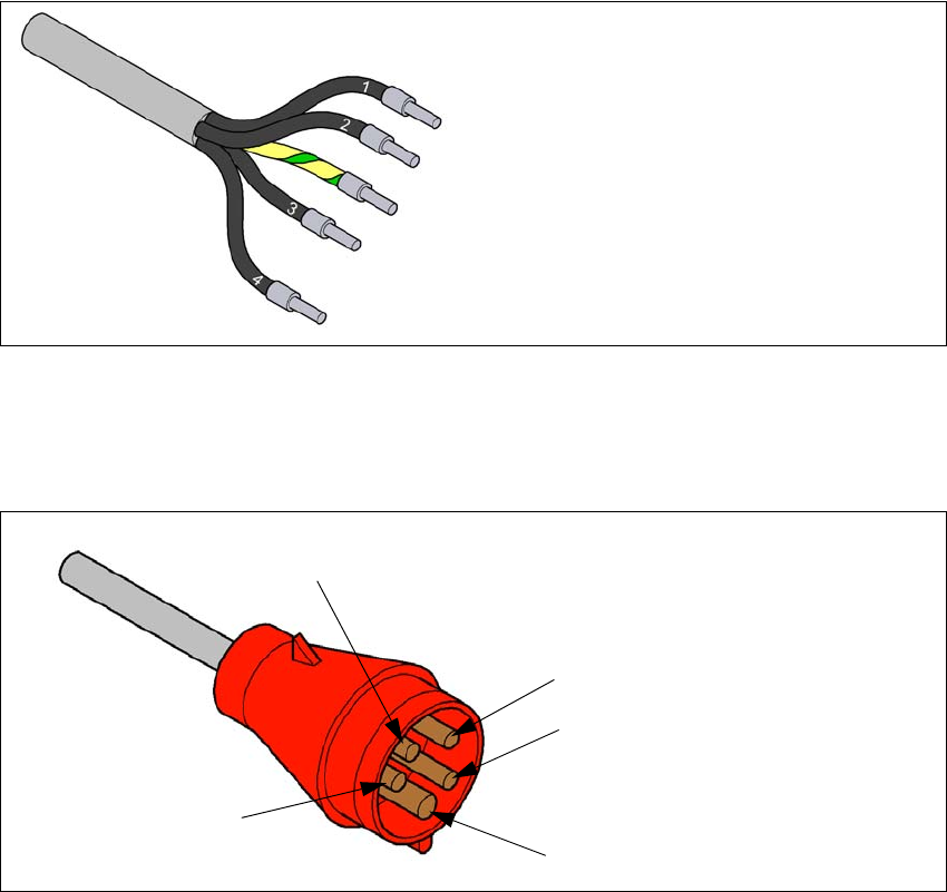
Fig. 4.2 - 3 Description of wires in the mains power cable
– The machine is configured for voltages of 380V AC, 400V AC or 415V AC.
The machine has a mains power cable WITH Cekon plug. 4
4
Fig. 4.2 - 4 Assignment in the Cekon plug
1 = (L1): three-phase
2 = (L2): three-phase
3 = (L3): three-phase
4 = (N): neutral conductor
green/yellow = (PE): conductor
PE
L1
L2
L3
N
4 Setting up and commissioning User manual SIPLACE X-Series
4.2 Infrastructure at the installation location From software version 706.1 SP1 Version 10/2014
236
4.2.3.5 Connecting the power supply cable
4
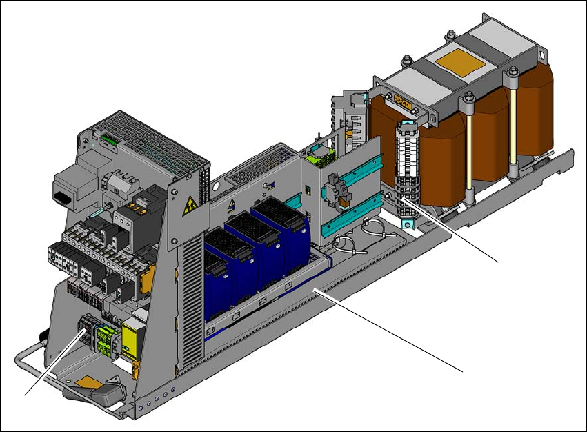
Fig. 4.2 - 5 Terminal panel for connecting the power cable
(1) Terminal panel (primary terminals for the three-phase transformer)
(2) Power supply unit
(3) Mains supply terminals
Crimp a ferrule onto each end of the wire.
Run the mains supply cable to the mains connection terminals (item 3).
Fix the cable to the mains connection terminals (item 3)
(L1): three-phase 4
(L2): three-phase 4
(L3): three-phase 4
(N): neutral conductor 4
(PE): PE conductor 4
Make sure that the bending radius is adequate. The wires must not be kinked.
Fix the mains supply cable with the help of cable ties.
(1)
(2)
(3)
User manual SIPLACE X-Series 4 Setting up and commissioning
From software version 706.1 SP1 Version 10/2014 4.2 Infrastructure at the installation location
237
4.2.3.6 Checking connections to the primary side of the three-phase transformer T1
The primary side of the three-phase transformer must be configured for the relevant supply volt-
age.
Check the terminal strip (1) to make sure that the primary end of the three-phase transformer
is correctly connected for the relevant supply voltage.
4
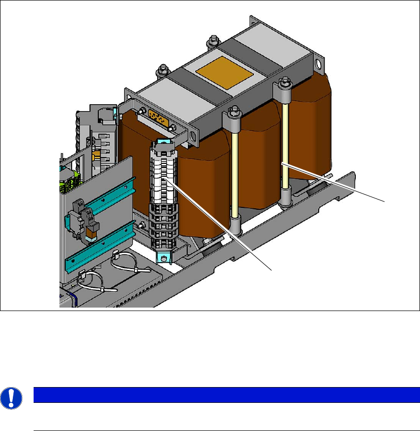
Fig. 4.2 - 6 Terminal panel for the primary side of the three-phase transformer T1
(1) Terminal panel with primary connections for the three-phase transformer T1
(2) Three-phase transformer
4
The following overview shows the connection options for the primary voltages of the three-phase
transformer.
PLEASE NOTE
The supply networks for North Japan (3 x 200 V~) and for the USA (
3 x 208 V~) are connected to the terminals for 3 x 204 V~.
(1)
(2)