00197004-04_UM_X-Serie-S_EN.pdf - 第408页
6 Station extensions User manual SIPLACE X-Series 6.17 Vision Teach Station From software version 706.1 SP1 Version 10/2014 408 6.17.1 Description The vision teach station is a system for c reating and t esting package f…
User manual SIPLACE X-Series 6 Station extensions
From software version 706.1 SP1 Version 10/2014 6.17 Vision Teach Station
407
6.17 Vision Teach Station
Item no. 00119788-xx Vision teach station
6
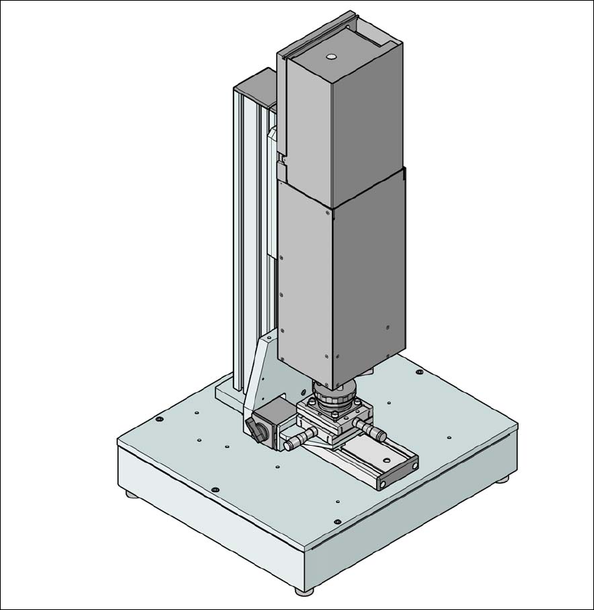
Fig. 6.17 - 1 Vision teach station with component camera, type 33
6 Station extensions User manual SIPLACE X-Series
6.17 Vision Teach Station From software version 706.1 SP1 Version 10/2014
408
6.17.1 Description
The vision teach station is a system for creating and testing package form descriptions for com-
ponents to be processed on SIPLACE placement machines.
The vision teach station essentially consists of the following components:
– Base module with electronic circuits and one or two component cameras
– Mini-tower PC
WINDOWS XP operating system 6
SIPLACE Vision image processing software 6
SIPLACE Pro database server 6
Camera interfaces: CAN bus card and camera bus card 6
The vision teach station is used to create and test descriptions for package forms for any place-
ment machine and to run component inspections.
The package form descriptions thus created may be stored in the SIPLACE Pro database on the
vision teach station and transferred to the SIPLACE Pro database of the production system. You
can also download vision screenshots from placement machines to the vision teach station for
analysis. Only multiple component measurements still have to be carried out on the placement
machine.
6.17.2 Benefits
The major advantage of this offline system is that it is totally independent of the production system,
and no production system resources have to be used for creating and testing package form de-
scriptions. As a result, there is no loss of productivity due to the description and testing of package
forms. The time taken to introduce new products can also be considerably reduced with this inde-
pendent system.

User manual SIPLACE X-Series Index
Edition 04/2014
409
Index
Symbols
"Head crash" label . . . . . . . . . . . . . . . . . . . . . . .67
"Switching on the SIPLACE line" flow chart . . .276
Numerics
24 mm X tape feeder module . . . . . . . . . . . . . .190
2D board code reader
. . . . . . . . . . . . . . . . . . . .363
2x8 mm X tape feeder module
. . . . . . . . . . . . .186
32 mm X tape feeder module
. . . . . . . . . . . . . .191
3D coplan
. . . . . . . . . . . . . . . . . . . . . . . . . . . . .395
3D coplanarity laser module
Accuracy
. . . . . . . . . . . . . . . . . . . . . . . . . .397
Component size
. . . . . . . . . . . . . . . . . . . . .397
Laser protection class
. . . . . . . . . . . . . . . .397
Maximum component height
. . . . . . . . . . .397
Maximum component size
. . . . . . . . . . . . .397
Maximum connector size
. . . . . . . . . . . . . .397
Min. ball diameter
. . . . . . . . . . . . . . . . . . . .397
Min. ball pitch
. . . . . . . . . . . . . . . . . . . . . . .397
Min. lead pitch
. . . . . . . . . . . . . . . . . . . . . .397
Min. lead width
. . . . . . . . . . . . . . . . . . . . . .397
Min. number of balls
. . . . . . . . . . . . . . . . . .397
Min. number of leads
. . . . . . . . . . . . . . . . .397
Placement head type
. . . . . . . . . . . . . . . . .397
technical data
. . . . . . . . . . . . . . . . . . . . . . .397
44 mm X tape feeder module
. . . . . . . . . . . . . .192
56 mm X tape feeder module
. . . . . . . . . . . . . .193
72 mm X tape feeder module
. . . . . . . . . . . . . .194
8 mm X tape feeder module
. . . . . . . . . . 185, 187
88 mm X tape feeder module
. . . . . . . . . . . . . .195
A
Abbreviations . . . . . . . . . . . . . . . . . . . . . . . . . . .43
Adapter for the X-Series feeder modules
202, 203,
. . . . . . . . . . . . . . . . . . . . . . . . . . . . . . . . . . .204
adapter plate for Label Presenter
. . . . . . . . . . .202
adapter plate for Reject Conveyor
. . . . . . . . . .204
adapter plate, 16.5 mm
. . . . . . . . . . . . . . . . . . .203
adapting the component trolley to the PCB conveyor
height
. . . . . . . . . . . . . . . . . . . . . . . . . . . . .261
Adjusting the empty tape duct to the component
height
. . . . . . . . . . . . . . . . . . . . . . . . . . . . 263
Advanced production
. . . . . . . . . . . . . . . . . . . 274
air cushion transport system
. . . . . . . . . . 244, 259
Alert
. . . . . . . . . . . . . . . . . . . . . . . . . . . . . . . . . 286
alert information, colors
. . . . . . . . . . . . . . . . . . 289
Allen wrench, size 10
. . . . . . . . . . . . . . . . . . . 244
Allen wrench, size 19
. . . . . . . . . . . . . . . . . . . 244
ambient conditions
Ambient pressure
. . . . . . . . . . . . . . . . . . . 121
Ambient conditions for machine operation
. . . 125
Ambient conditions for packaging, transportation
and storage
. . . . . . . . . . . . . . . . . . . . . . . . 125
Ambient pressure
. . . . . . . . . . . . . . . . . . . . . . 121
Angular accuracy
. . . . . . . . . . . . . . . . . . . . . . 117
A-Placement
. . . . . . . . . . . . . . . . . . . . . . . . . . . 43
Assembly position for the stationary cameras
IC and FC camera
. . . . . . . . . . . . . . . . . . 175
Assembly positions of MultiStar in the machine
149
assembly positions of SIPLACE MultiStar
. . . 147
Atmospheric humidity
. . . . . . . . . . . . . . . . . . . 121
authorized employees.
. . . . . . . . . . . . . . . . . . 108
Automatic circuit breaker F1
. . . . . . . . . . . . . . 104
Automatic width adjustment
. . . . . . . . . . . . . . 170
Avoiding track errors
. . . . . . . . . . . . . . . . . . . . 319
B
basic view . . . . . . . . . . . . . . . . . . . . . . . . . . . . 281
Boards being processed
. . . . . . . . . . . . . . . . . 281
buttons . . . . . . . . . . . . . . . . . . . . . . . . . . . . . . . 84