00197004-04_UM_X-Serie-S_EN.pdf - 第394页
6 Station extensions User manual SIPLACE X-Series 6.9 SIPLACE High-Force Head From software version 706.1 SP1 Version 10/2014 394 6.9 SIPLACE High-Force Head Item no. 001 1 9736-xx High-Force Head This item number only a…
User manual SIPLACE X-Series 6 Station extensions
From software version 706.1 SP1 Version 10/2014 6.8 Docking station for the component trolley of the SIPLACE X-Series
393
6
Unscrew the two screwed connections (item 3 in fig. 6.8 - 5, page 391).
Loosen the two other screwed connections (item 2 in fig. 6.8 - 5, page 391).
Remove the two M8 hexagonal nuts and washers (item 4 in fig. 6.8 - 5, page 391).
Hold the COT insert by its side (item 10 in fig. 6.8 - 5, page 391) and remove the two hexagon
socket-head screws M8x40 here.
Swivel the COT insert to the next highest position.
Fasten the side panel at this point. Tighten the nuts loosely to do this.
Hold the COT insert by the FCU (item 12 in fig. 6.8 - 5, page 391) and remove the screwed
connections at item 2 in fig. 6.8 - 5
, page 391.
Swivel the COT insert to the next highest position.
Fasten the side panel at this point.
Check that all screwed connections at items 2, 3 and 4 are tightened firmly.
Fasten the right and left guidances (item 8 in fig. 6.8 - 5, page 391) with the hexagon socket-
head screw M8x18 (item 9 in fig. 6.8 - 5
, page 391).
6
CAUTION
Risk of damage!
When raising and lowering the COT insert, cables can be damaged.
When raising and lowering the COT insert, make sure that no cables are damaged.
PLEASE NOTE
If you want to lower the COT insert to a different height, follow the above instructions
in reverse order.

6 Station extensions User manual SIPLACE X-Series
6.9 SIPLACE High-Force Head From software version 706.1 SP1 Version 10/2014
394
6.9 SIPLACE High-Force Head
Item no. 00119736-xx High-Force Head
This item number only applies when ordering a new placement machine with a high force
head instead of a standard TwinStar. 6
6.9.1 Description
The SIPLACE high force head is an advanced development of the standard TwinStar. It can pro-
cess the same component range and also offers the possibility of achieving set-down forces up to
30 N. The SIPLACE high force head can use all the same nozzles and grippers as the standard
TwinStar.
6.9.2 Technical data
6
Al other technical data are identical for the TwinStar and high force head (see section 3.5.7.2,
page 156
).
Programmable set-down force 2.0 N to 10 N ± 10 %
greater than 10 N up to 30 N ± 15 %
User manual SIPLACE X-Series 6 Station extensions
From software version 706.1 SP1 Version 10/2014 6.10 3D coplanarity laser module
395
6.10 3D coplanarity laser module
Item no. 519807-xx 3-D coplan, X2 S / X3 S / X4 S
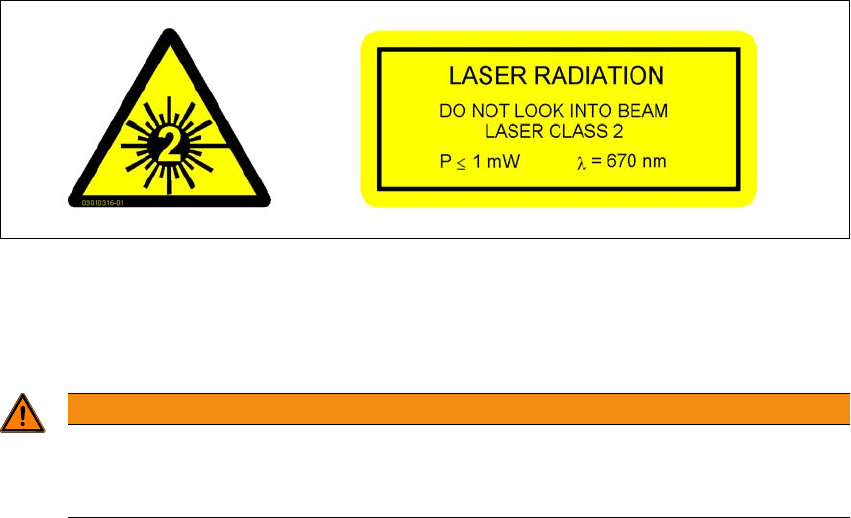
6.10.1 Safety instructions for coplanarity module sensor
The sensor works with a semiconductor laser which has a wave length of 670 nm (visible/red).
The maximum optical output is 1 mW.
This sensor is classified as laser class 2.
– When using the sensor, always observe the applicable VDE 0837 regulations regarding "Ra-
diation safety of laser devices" and the"Laser radiation" (BGV B2) accident prevention regu-
lation applicable in Germany.
– Also observe the accident prevention regulations of your own country!
The following labels are attached to the front and back of the sensor:
6
Fig. 6.10 - 1 Laser class 2 classification for the sensor
Despite the low laser output, avoid looking directly at the laser beam. As the beam is visible, the
natural reflex of your eyelids will protect your eyes from the beam.
6
WARNING
The housing of the optical sensor may only be opened by authorized personnel.
For repair and service work, always send the sensors to ASM Assembly Systems
GmbH&Co.KG.