00197004-04_UM_X-Serie-S_EN.pdf - 第240页
4 Setting up and commissioning User manual SIPLACE X-Series 4.3 Setting up the machine From software version 706.1 SP1 Version 10/2014 240 4.3 Setting up the machine 4.3.1 W arning instructions 4 4 4 4 4 WARNING Observe …
User manual SIPLACE X-Series 4 Setting up and commissioning
From software version 706.1 SP1 Version 10/2014 4.2 Infrastructure at the installation location
239
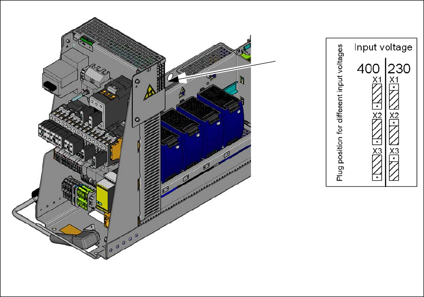
4.2.3.7 Checking the inrush current limitation jumpers
The inrush current limiter of the transformer (A2) is connected in the same manner for all supply
voltages. The connectors must all be plugged into the position for input voltage 230V.
4
Fig. 4.2 - 7 Position of the board and connectors for the inrush current limitation
(1) Position of the inrush current limitation (A2)
(2) Configuration schema
Check the connector assignment for the inrush current limiter of the transformer. The connec-
tors for all mains voltages need to be plugged into the Input Voltage 230V point.
(1)
(2)

4 Setting up and commissioning User manual SIPLACE X-Series
4.3 Setting up the machine From software version 706.1 SP1 Version 10/2014
240
4.3 Setting up the machine
4.3.1 Warning instructions
4
4
4
4
4
WARNING
Observe the applicable accident prevention regulations!
Only SIPLACE engineers or qualified people are permitted to set up and commission the
machine.
The applicable accident prevention regulations concerning the transportation of
heavy goods must be followed.
WARNING
Risk of injury during assembly work to the underside of the machine!
There is a risk of injury during assembly work to the underside of the machine!
Secure the machine using suitable measures. The fork-lift must not be used as the
only support.
WARNING
Risk of injury during assembly work!
Incorrect positioning of gantries during assembly restricts the head clearance and can
lead to injuries.
Take care that the gantries are positioned over the board conveyor area.
WARNING
Height adjustment of machine!
Two people will be needed to adjust the height of the machine:
– One person completes the required assembly work
– The other person watches the stability of the raised machine during assembly.
WARNING
DANGER OF CRUSHING!
Risk of crushing feet when transporting the machine.
Wear specially reinforced shoes.
User manual SIPLACE X-Series 4 Setting up and commissioning
From software version 706.1 SP1 Version 10/2014 4.3 Setting up the machine
241
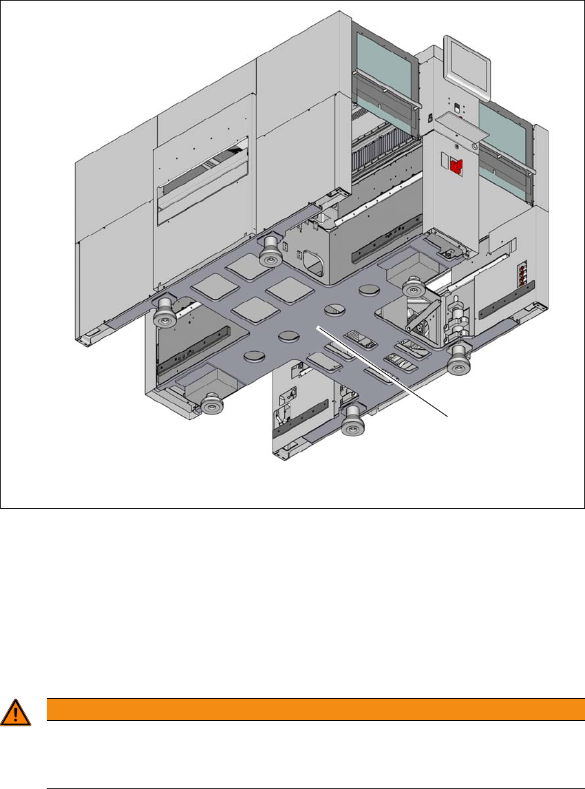
4.3.2 Lifting and transporting the machine with the fork lift truck
4
Fig. 4.3 - 1 Contact surfaces - forks parallel to the direction of PCB transport (example of SIPLACE X2 S / X3 S / X4
S shown)
(1) Contact surface for fork lift truck forks
Position the fork-lift truck at right angles to the PCB conveyor and open the forks until the con-
tact surfaces of the machine lie evenly on the forks.
Please note the following points before you raise the machine in order to avoid irreversible dam-
age to the machine:
4
WARNING
Aligning the forks
– The forks must be aligned parallel to the PCB conveyor.
– The forks must be aligned to the center of the machine.
(1)