00197004-04_UM_X-Serie-S_EN.pdf - 第94页
2 Operational safety User manual SIPLACE X-Series 2.6 Safety features From software version 706.1 SP1 Version 10/2014 94 2.6.6 Hand guards at the locat ions with dummy feeders 2 Fig. 2.6 - 1 1 Hand guard on the component…
User manual SIPLACE X-Series 2 Operational safety
From software version 706.1 SP1 Version 10/2014 2.6 Safety features
93
2
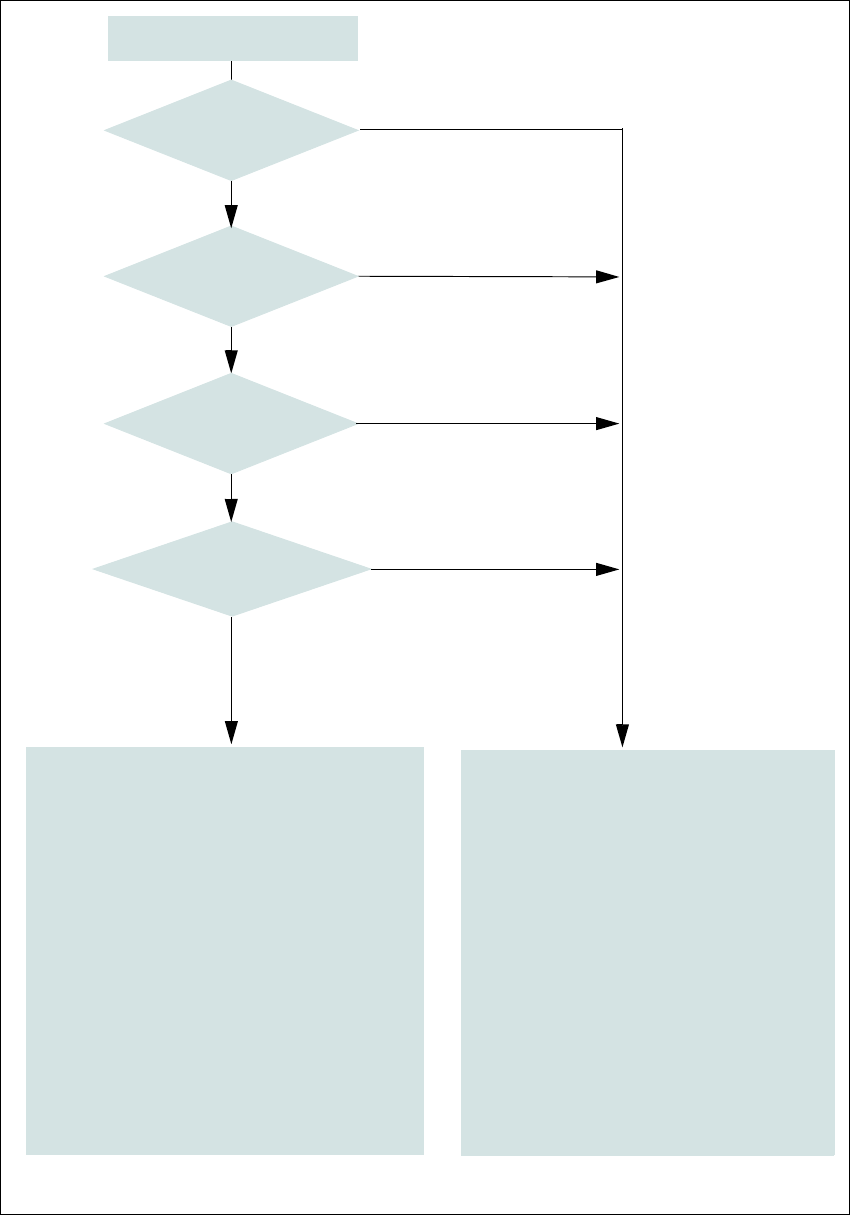
Fig. 2.6 - 10 EMERGENCY STOP loop
Start button pressed
No
No
Yes
No
No
Yes
Yes
2
Active
SSK
a
No
Voltage
Y axis 0 V-
X axis 0 V-
Star axis 0 V-
DP axis 42 V-
Z axis (C&P, TH) 42 V-
Z axis (CPP) 0 V-
Active
PCB conveyor No
Lifting table No
PCB clamping No
Width adjustment No
Tape cutter No
Component trolley feeding device Yes
a) SSK protective contactor combination K3
Yes
Compressed
air min. 0.5 MPa
(5.0 bar)?
EMERGENCY STOP button
pressed?
- Protective cover and/or
service flap open?
Component trolley
EMERGENCY STOP circuit
interrupted?
0
Active
SSK
a
Yes
Voltage
Y axis 260 V-
X axis 260 V-
Star axis 150 V-
DP axis 42 V-
Z axis (C&P, TH) 42 V-
Z axis (CPP) 150 V-
Active
PCB conveyor Yes
Lifting table Yes
PCB clamping Yes
Width adjustment Yes
Tape cutter. Yes
Component trolley feeding device Yes
2 Operational safety User manual SIPLACE X-Series
2.6 Safety features From software version 706.1 SP1 Version 10/2014
94
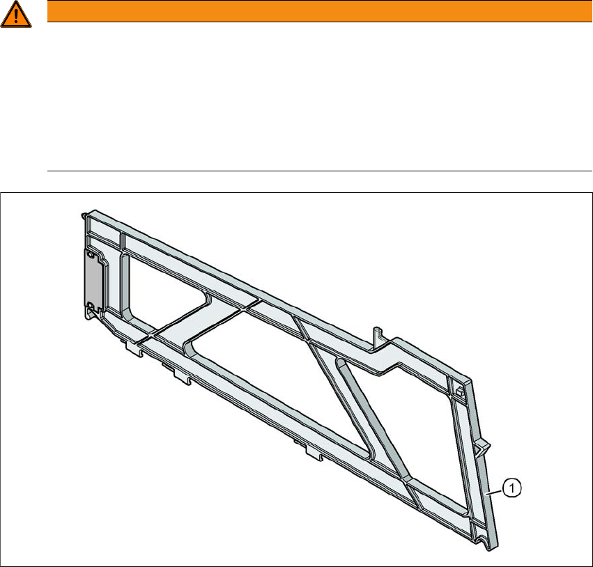
2.6.6 Hand guards at the locations with dummy feeders
2
Fig. 2.6 - 11 Hand guard on the component trolley locations
2
(1) Dummy feeder SIPLACE X, item no. 00141226-xx
WARNING
Operatio nal
Operational safety by occupying every second location!
The operational safety of the component trolley in the SIPLACE X-Series is ensured if at
least every second free location is occupied with a feeder module or hand guard (dummy
feeder).
Fit a hand guard with fiducial at locations 2 and 4.
Even when configuring a holder for waffle pack trays, secure every second location
with a hand guard.
User manual SIPLACE X-Series 2 Operational safety
From software version 706.1 SP1 Version 10/2014 2.7 Residual voltages and discharge times in the machine
95
2.7 Residual voltages and discharge times in the machine
If the EMERGENCY STOP button is pressed or the machine is switched off, the 260 VDC link volt-
age for the gantry axes and the 150 VDC link voltage for the star axes are reduced to harmless
residual voltages in a very short time.
2
2
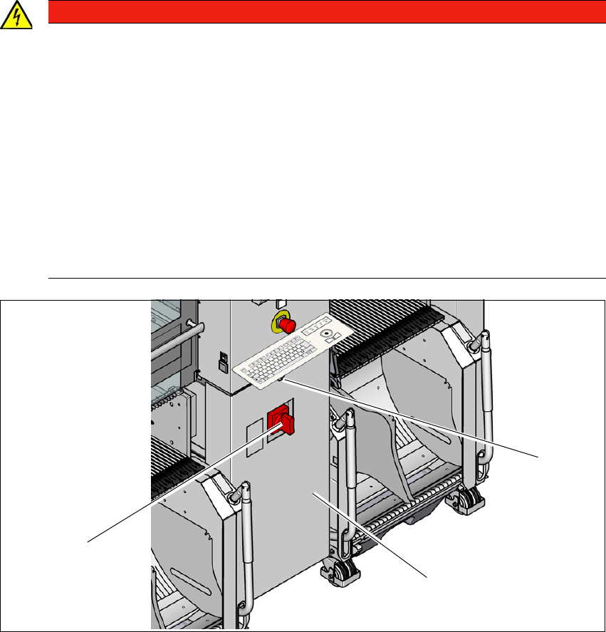
Fig. 2.7 - 1 Power supply unit (example of SIPLACE X2 S / X3 S / X4 S shown)
(1) Main switch
(2) Power supply unit behind the cover
(3) Padlock with bolt in the cover
DANGER
Dangerous voltage levels!
The machine is supplied with 3 x 200 V~, 3 x 208 V~, 3 x 220 V~, 3 x 230 V~,
3 x 380 V~, 3 x 400 V~ or 3 x 415 V~ ± 5 %, 50/60 Hz mains voltage. This means that
some parts of the system carry potentially lethal voltages - even when switched off at the
main power switch.
Incorrect handling of this machine can therefore result in death or severe injury or con-
siderable damage to equipment.
Always follow the applicable accident prevention and DIN regulations (particularly
EN 60204, part 1 or IEC 60204, part 1) and the applicable regulations in your own
country.
The covers over the power supply unit may ONLY be opened by appropriately qual-
ified and trained personnel.
(3)
(1)
(2)