00197004-04_UM_X-Serie-S_EN.pdf - 第232页
4 Setting up and commissioning User manual SIPLACE X-Series 4.2 Infrastructure at the installation location From software ve rsion 706.1 SP1 Version 10/2014 232 4.2.2.2 Compressed air connection on the machine 4 Fig. 4.2…

User manual SIPLACE X-Series 4 Setting up and commissioning
From software version 706.1 SP1 Version 10/2014 4.2 Infrastructure at the installation location
231
4.2 Infrastructure at the installation location
4
4.2.1 Recommendations for foundation quality
The foundation on which the machine is installed must be firm and level, as dynamic forces could
cause vibrations when the machine is operated. The degree of vibration depends on the construc-
tion of the foundation. The following are suitable provided that the floor loading parameters, etc.,
are not exceeded:
– Reinforced concrete ceiling constructions, e.g. ceilings in production halls
– Reinforced concrete floor slabs, e.g. concrete floors in production halls without a basement
– Rooms with double floors, provided that a stable foundation is included in the space between
them. The same setup conditions apply to this intermediate foundation, which can be made
from steel girders or concrete.
4
4.2.1.1 Maximum ground levelness
The floor underneath the machine may not exceed an incline of 0.63%. This corresponds to an
incline of 5 mm over a distance of 800 mm (e.g. the width of a changeover table).
4.2.1.2 Machine weight and floor loading
The machine weight and floor loading values can be found in section 3.3.1, page 125.
4.2.2 Compressed air supply
4.2.2.1 Checking the compressed air supply
Check whether the compressed air supply complies with the prescribed machine specifications
(see table in section 3.2
, page 121).
Record the compressed air characteristics at the installation location.
4
PLEASE NOTE
Also observe the document "Network and compressed air configuration for SMD sys-
tems" (German+English, Item No. 00197548-xx), which is supplied with your SIPLACE
machine.
WARNING
Risk of injuries!
Risk of injuries from pressurized compressed air lines.
NEVER detach compressed air lines while they are still pressurized.
4 Setting up and commissioning User manual SIPLACE X-Series
4.2 Infrastructure at the installation location From software version 706.1 SP1 Version 10/2014
232
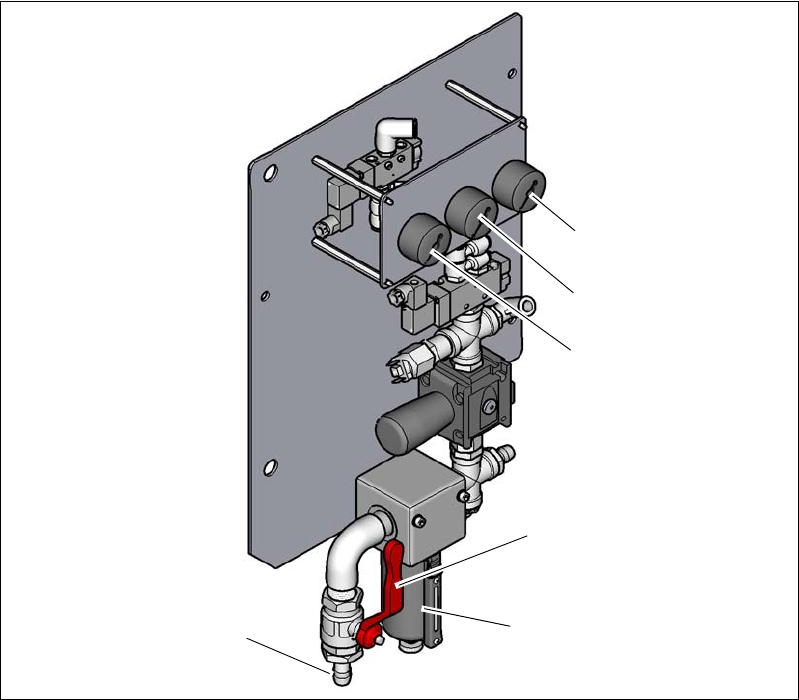
4.2.2.2 Compressed air connection on the machine
4
Fig. 4.2 - 1 Compressed air unit on the machine
Legend for fig.4.2 - 1
(1) Manometer for the machine component supply pressure
Target pressure: 0.5 ± 0.025 MPa, 5 ± 0.25 bar (display range 0 - 1.0 MPa, 0 - 10 bar)
(2) Manometer for supply pressure of gantries 1 to 4
Target pressure: 0.46 ± 0.01 MPa, 4.6 ± 0.1 bar (display range 0 - 1.0 MPa, 0 - 10 bar)
(3) Manometer for inlet pressure
Target pressure: 0.5 - 1.0 MPa, 5 - 10 bar (display range: 0 - 1.0 MPa, 0 - 10 bar)
(4) Stop valve in the "OPEN" position
(5) Compressed air filter
(6) Compressed air connection
(6)
(1)
(2)
(3)
(5)
(4)

User manual SIPLACE X-Series 4 Setting up and commissioning
From software version 706.1 SP1 Version 10/2014 4.2 Infrastructure at the installation location
233
4.2.3 Main power supply
4
Fig. 4.2 - 2 Position of power supply on the machine (example of SIPLACE X2 S / X3 S / X4 S shown)
(1) Lock
(2) Main power switch secured to prevent switching on again
(3) Power supply unit (behind the cover)
(4) Mains connection cable
4.2.3.1 Danger notes
4
(1)
(2)
(3)
(4)
DANGER
Dangerous voltage levels!
The machine is supplied with 3 x 200 V~, 3 x 208 V~, 3 x 220 V~, 3 x 230 V~,
3 x 380 V~, 3 x 400 V~ or 3 x 415 V~ ± 5 %, 50/60 Hz mains voltage. This means that
some parts of the system carry potentially lethal voltages - even when switched off at the
main power switch.
Incorrect handling of this machine can therefore result in death or severe injury or con-
siderable damage to equipment.
Always follow the applicable accident prevention and DIN regulations (particularly
EN 60204, part 1 or IEC 60204, part 1) and the applicable regulations in your own
country.
The covers over the power supply unit may ONLY be opened by appropriately qual-
ified and trained personnel.