00197004-04_UM_X-Serie-S_EN.pdf - 第99页
User manual SIPLACE X-Series 2 Operational safety From software version 706.1 SP1 Version 10/2014 2.8 Disabli ng the compressed air supply and discharging the pressur e 99 2.8 Disabling the compressed air supply and disc…
2 Operational safety User manual SIPLACE X-Series
2.7 Residual voltages and discharge times in the machine From software version 706.1 SP1 Version 10/2014
98
2.7.2 Residual voltages and discharge times after pressing the EMERGENCY
STOP button
2
2
2
Measuring point on the X200
distributor terminal block
Voltage in
normal mode
Residual voltage after
EMERGENCY STOP
Discharge
times
X200 - 4.a 150 V- < 10 VDC < 2s
X200-13.a 24 V- < 10 VDC < 2s
Interface-machine cable tree Voltage in
normal mode
Residual voltage if
main switch OFF or
power failure
Discharge
times
X21 - 1 260 V- < 10 VDC < 2s
X31 - 1 150 V- < 10 VDC < 2s
A8 ( positive connection) 42 V- (permanent) < 10 VDC < 2s
X18 - 7 42 V- (switched) < 10 VDC < 2s
X17 - 1 24 V- < 10 VDC < 2s
CAUTION
Data loss!
To avoid losing data, assess the following criteria before switching off your machine
(apart from in emergencies):
– Has the machine finished transmitting machine, setup and panel data?
– Has the machine finished processing the PCB?
– Has the machine completed the run-up phase?

User manual SIPLACE X-Series 2 Operational safety
From software version 706.1 SP1 Version 10/2014 2.8 Disabling the compressed air supply and discharging the pressure
99
2.8 Disabling the compressed air supply and discharging
the pressure
The compressed air working pressure of the machine is set to 0.50 ± 0.025 MPa (5.0 ± 0.25 bar).
The position of the compressed air unit is shown at item 1 in fig. 2.8 - 1
, page 100. The supply of
compressed air to the machine can be interrupted with the shutoff valve (item 2 in fig. 2.8 - 1
, page
100
).
Use the machine key to release the cover lock.
Lift the cover (see fig. 2.8 - 1, page 100 ).
Turn the lever of the shutoff valve (item 1 of fig. 2.8 - 1, page 100) from the vertical to the
horizontal position.
Monitor the operating pressure manometer (item 5 in fig. 2.8 - 1, page 100 ). When the ma-
chine is switched on, the pressure discharges to 0 MPa (0 bar) within 1 minute.
2
CAUTION
Interruption to compressed air supply!
When the machine is switched on, do not use the stop valve to interrupt the com-
pressed air supply for more than 30 minutes.
If you need to shut off the pneumatic system for longer in order to carry out preven-
tive maintenance or servicing work, you must switch the machine off at the main
switch and disconnect it from the power supply.
2 Operational safety User manual SIPLACE X-Series
2.8 Disabling the compressed air supply and discharging the pressure From software version 706.1 SP1 Version 10/2014
100
2
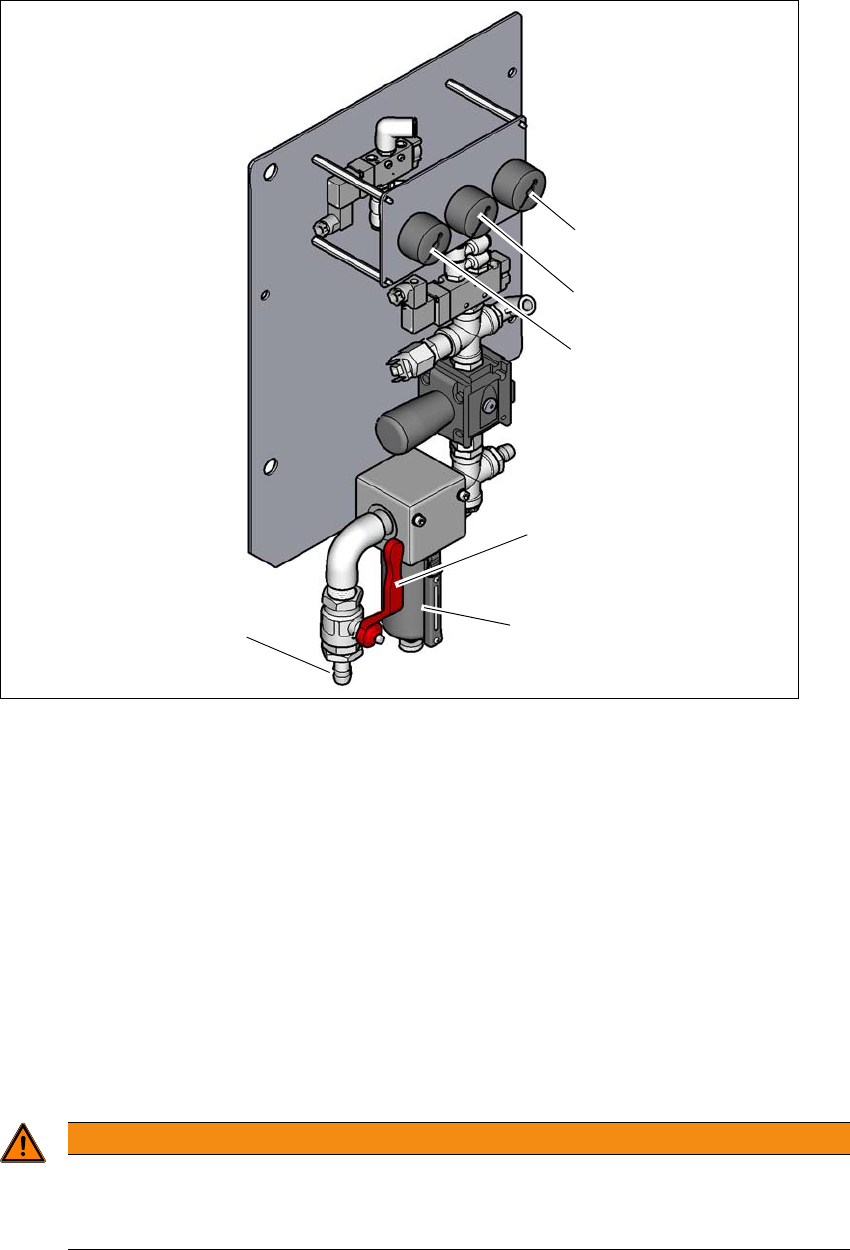
Fig. 2.8 - 1 Compressed air unit on the machine
Legend for fig. 2.8 - 1
(1) Manometer for the machine component supply pressure
Target pressure: 0.5 ± 0.025 MPa, 5 ± 0.25 bar (display range 0 - 1.0 MPa, 0 - 10 bar)
(2) Manometer for supply pressure of gantries 1 to 4
Target pressure: 0.46 ± 0.01 MPa, 4.6 ± 0.1 bar (display range 0 - 1.0 MPa, 0 - 10 bar)
(3) Manometer for inlet pressure
Target pressure: 0.5 - 1.0 MPa, 5 - 10 bar (display range: 0 - 1.0 MPa, 0 - 10 bar)
(4) Stop valve in the "OPEN" position
(5) Compressed air filter
(6) Compressed air connection
2
WARNING
Risk of injuries!
Risk of injuries from pressurized compressed air lines.
NEVER detach compressed air lines while they are still pressurized.
(6)
(1)
(2)
(3)
(5)
(4)