00197004-04_UM_X-Serie-S_EN.pdf - 第400页
6 Station extensions User manual SIPLACE X-Series 6.12 Component camera for the MultiStar From software ve rsion 706.1 SP1 Version 10/2014 400 6.12 Component camera for the MultiS t ar 6.12.1 Component camera, st ationar…

User manual SIPLACE X-Series 6 Station extensions
From software version 706.1 SP1 Version 10/2014 6.11 Component camera for the TwinStar, FC camera
399
6.11.3 Technical data
6
6
6
6
6.11.4 Position
The position of the stationary component cameras and the associated configurations are de-
scribed
in section 3.8.2
, from page 175.
Component dimensions 0.2 mm x 0.2 mm up to 16 mm x 16 mm for single component
measurement
Component range 0402 to SO, PLCC, QFP, sockets, plugs, BGA, special components,
bare dies, flip-chips, shields
Min. lead pitch 0.25 mm
Min. lead width 0.1 mm
Min. ball pitch 0.14 mm
Min. ball diameter 0.08 mm
Field of vision 19.4 mm x 19.4 mm
Illumination type Front-illumination (6 levels, programmable as required)
6 Station extensions User manual SIPLACE X-Series
6.12 Component camera for the MultiStar From software version 706.1 SP1 Version 10/2014
400
6.12 Component camera for the MultiStar
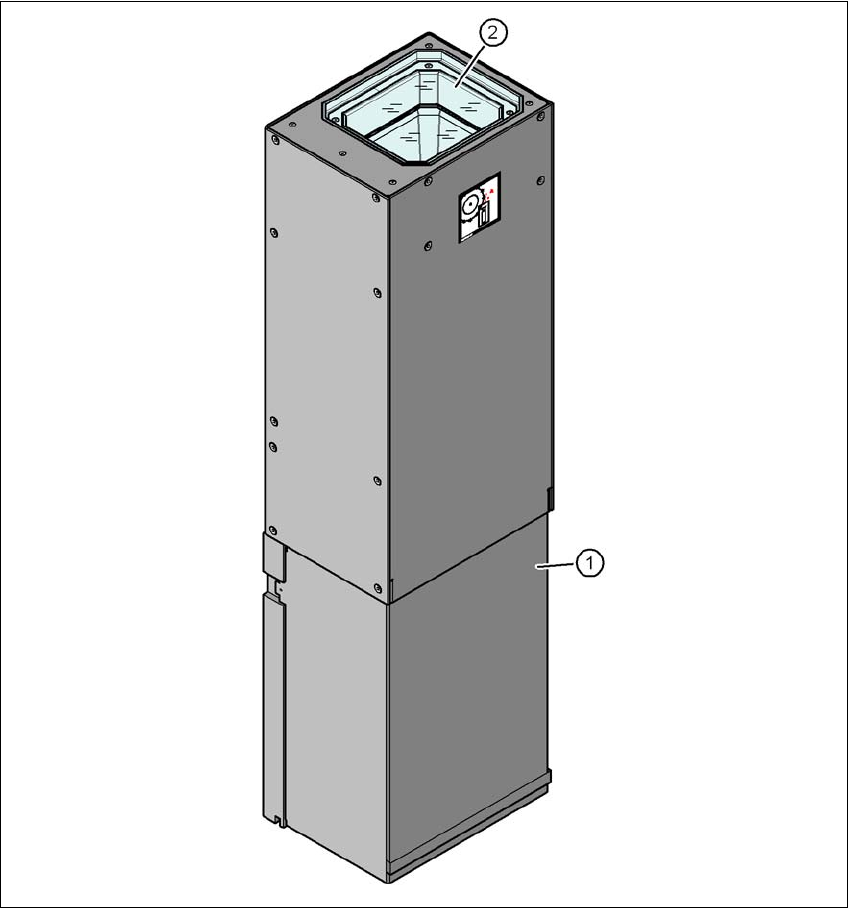
6.12.1 Component camera, stationary P&P, type 33, 55 x 45, digital
Item no. 00519902-xx Stationary camera for the CPP head, type 33
6
Fig. 6.12 - 1 Structure for the stationary P&P component camera, type 33, 55 x 45, digital
(1) Camera housing with integral camera and camera amplifier
(2) Glass plate - illumination and lens levels below

User manual SIPLACE X-Series 6 Station extensions
From software version 706.1 SP1 Version 10/2014 6.13 Siemens interface
401
6.12.1.1 Technical data
6
6
6.12.1.2 Position
The position of the stationary component cameras and the associated configurations are de-
scribed
in section 3.8.2
, from page 175.
6.13 Siemens interface
Item no. 00116808-xx SIPLACE interface
The conveyor interface on the placement machines from the X-Series is configured to the SMEMA
standard. It is, however, still possible to use this interface in accordance with the Siemens stan-
dard. This is a significant benefit when an X-Series machine is to be integrated into older SIPLACE
lines, in which case it would not be necessary to retrofit the older machines to conform to the
SMEMA standard.
Simply configure the conveyor interface of the X-Series machines to the Siemens standard and
connect the machines using the associated interface cable.
Component dimensions 0.5 mm x 0.5 mm to 55 mm x 45 mm
Component range 0402, MELF, SO, PLCC, QFP, electrolytic capacitors, BGA
Min. lead pitch 0.3 mm
Min. lead width 0.15 mm
Min. ball pitch 0.35 mm
Min. ball diameter 0.2 mm
Field of vision 65 mm x 50 mm
Illumination type Front-illumination (6 levels, programmable as required)