00197004-04_UM_X-Serie-S_EN.pdf - 第89页
User manual SIPLACE X-Series 2 Operational safety From software version 706.1 SP1 Version 10/2014 2.6 Safety features 89 2.6.4 Position of protective cont actor combination and service socket 2 Fig. 2.6 - 8 Position of p…

2 Operational safety User manual SIPLACE X-Series
2.6 Safety features From software version 706.1 SP1 Version 10/2014
88
EMERGENCY STOP button with forced locking (item 5 in fig. 2.6 - 5, page 84 and item 1 in fig.
2.6 - 6, page 85) 2
The EMERGENCY STOP button is red and latches in the ON position when pressed. When you
press the EMERGENCY STOP button, the switching contact of the EMERGENCY STOP circuit
opens and the protective contactor combination (K6) trips. The link voltage (260 VDC) for the gan-
try axes and the link voltage (150 VDC) for the star axes is switched off. The servo amplifiers for
the DP and Z axes are still supplied with 42 VDC. The signaling contact of the EMERGENCY
STOP button opens and the message "EMERGENCY STOP pressed" appears on the screen.
The following modules are deactivated:
– PCB conveyor
– PCB clamping
– Width adjustment
– PCB stopper
– Tape cutter (control via Feeder Control Unit prevented)
– Safety valve for the tape cutter
2
Protective cover switch 1 to 4 (items 1 to 4 in fig. 2.6 - 7, page 86) 2
These switches check whether the protective covers are closed. When they are closed, the
EMERGENCY STOP contact and the signaling contact are closed. If one of the covers is opened,
the EMERGENCY STOP contact and the signaling contact will open. Individual components are
disabled or remain enabled (see fig. 2.6 - 10
, page 93 ).
Protective cover switch for service flap (optional) 2
This switch checks whether the service flap is closed. When they are closed, the EMERGENCY
STOP contact and the signaling contact are closed. If the service flap is opened, the EMER-
GENCY STOP contact and the signaling contact will open. Individual components are disabled or
remain enabled (see fig. 2.6 - 10
, page 93 ).
PLEASE NOTE
Placement is interrupted and can then either be continued or canceled once the machine
is working correctly again.
User manual SIPLACE X-Series 2 Operational safety
From software version 706.1 SP1 Version 10/2014 2.6 Safety features
89
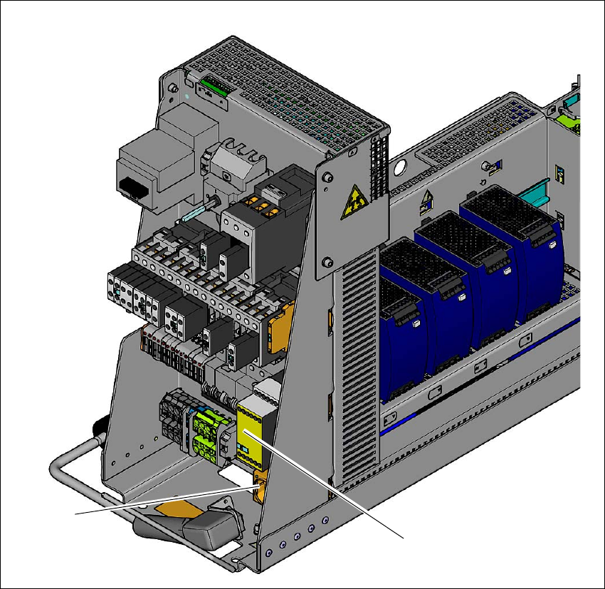
2.6.4 Position of protective contactor combination and service socket
2
Fig. 2.6 - 8 Position of protective contactor combination and service socket
2
(1) Protective contactor combination
(2) Service socket
(2)
(1)

2 Operational safety User manual SIPLACE X-Series
2.6 Safety features From software version 706.1 SP1 Version 10/2014
90
Protective contactor combination K6 (item 1 in fig. 2.6 - 8, page 89) 2
The protective contactor combination is contained in the power supply unit. It is used to monitor
the EMERGENCY STOP circuits and safety equipment.
There are three conditions that must be fulfilled in order to activate the protective contactor com-
bination:
– The "software release" or "Control ON" signal must be issued.
– The EMERGENCY STOP loop must be closed.
– The start button must have been pressed.
The front side of the protective contactor combination has three green LEDs for the operating dis-
play (see fig. 2.6 - 9
, page 91 )
– The "Power" LED indicates that voltage is present.
– The "Channel 1" and "Channel 2" LEDs shine if the start button has been pressed, the EMER-
GENCY STOP circuit is closed and the signaling circuit has not indicated any error states.
Service socket (item 2 in fig. 2.6 - 8, page 89) 2
The service socket is contained in the power supply unit and is protected by the cover. It can only
be used if the machine is connected to the main power supply via a 5-wire connection (L1, L2, L3,
N, and PE). If a 4-wire connection is used, e.g. without N, the socket cannot be used.
2
WARNING
Safety instructions about lethal voltages!
Always follow the safety instructions concerning potentially lethal voltages - even
when the machine is switched off. (See section 2.1.3
from page 46 and section
2.6.3.3
from page 87 .