00197004-04_UM_X-Serie-S_EN.pdf - 第397页
User manual SIPLACE X-Series 6 Station extensions From software version 706.1 SP1 Version 10/2014 6.10 3D coplanarity la ser module 397 6.10.3 T echnical dat a 6 Components QFP, SO, BGA, Gullwing, connector Accuracy *a ±…
6 Station extensions User manual SIPLACE X-Series
6.10 3D coplanarity laser module From software version 706.1 SP1 Version 10/2014
396
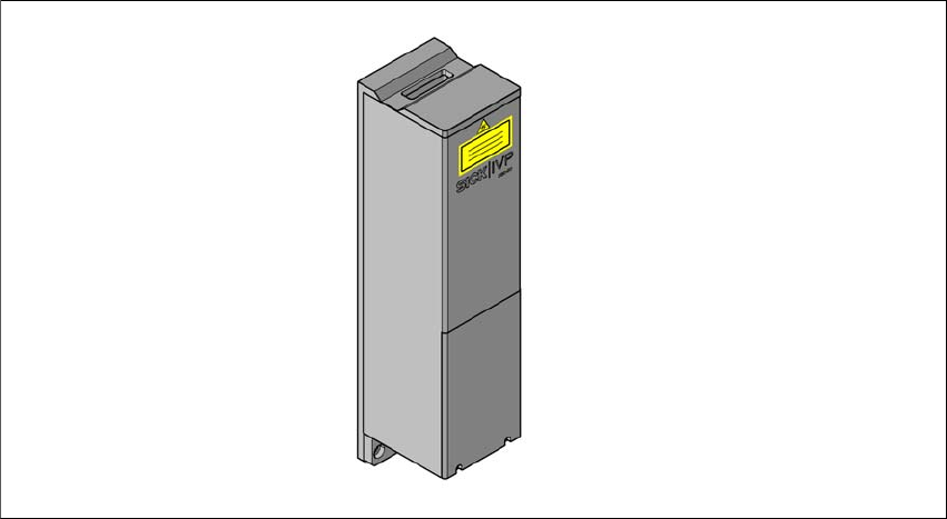
6.10.2 Description
The 3D coplanarity laser module works with a line of laser light. This enables you to generate and
analyze the height profile of a two-dimensional arrangement of component leads e.g. BGA, QFP
etc. This analysis provides data about the coplanarity (contact plane) and collinearity (contact line
straightness) of component leads or balls.
6
Fig. 6.10 - 2 3D coplanarity laser module

User manual SIPLACE X-Series 6 Station extensions
From software version 706.1 SP1 Version 10/2014 6.10 3D coplanarity laser module
397
6.10.3 Technical data
6
Components QFP, SO, BGA, Gullwing, connector
Accuracy
*a
± 15 μm (3), ± 20 μm (4)
Maximum component size 50 x 50 mm²
Maximum component height 17 mm
BGA component shape
Min. ball diameter
Min. ball pitch
Min. number of balls
400 m
800 m
6
Gullwing component shape
Min. lead width
*b
Min. lead pitch
Min. number of leads
300 m
500 m
5
Maximum connector size 120 x 20 mm²
Connector (Gullwing)
Min. lead width
b
Min. lead pitch
Min. number of leads
300 m
500 m
5
Placement head type TwinHead
Laser protection class
3D coplanarity sensor
Placement machine
3B
2
*)a Per ball/lead
*)b Contact your local product manager for details of smaller lead widths
For more details, refer to the "Assembly Instructions 3D Sensor", German+English [Item. no.
00197084-xx]
6 Station extensions User manual SIPLACE X-Series
6.11 Component camera for the TwinStar, FC camera From software version 706.1 SP1 Version 10/2014
398
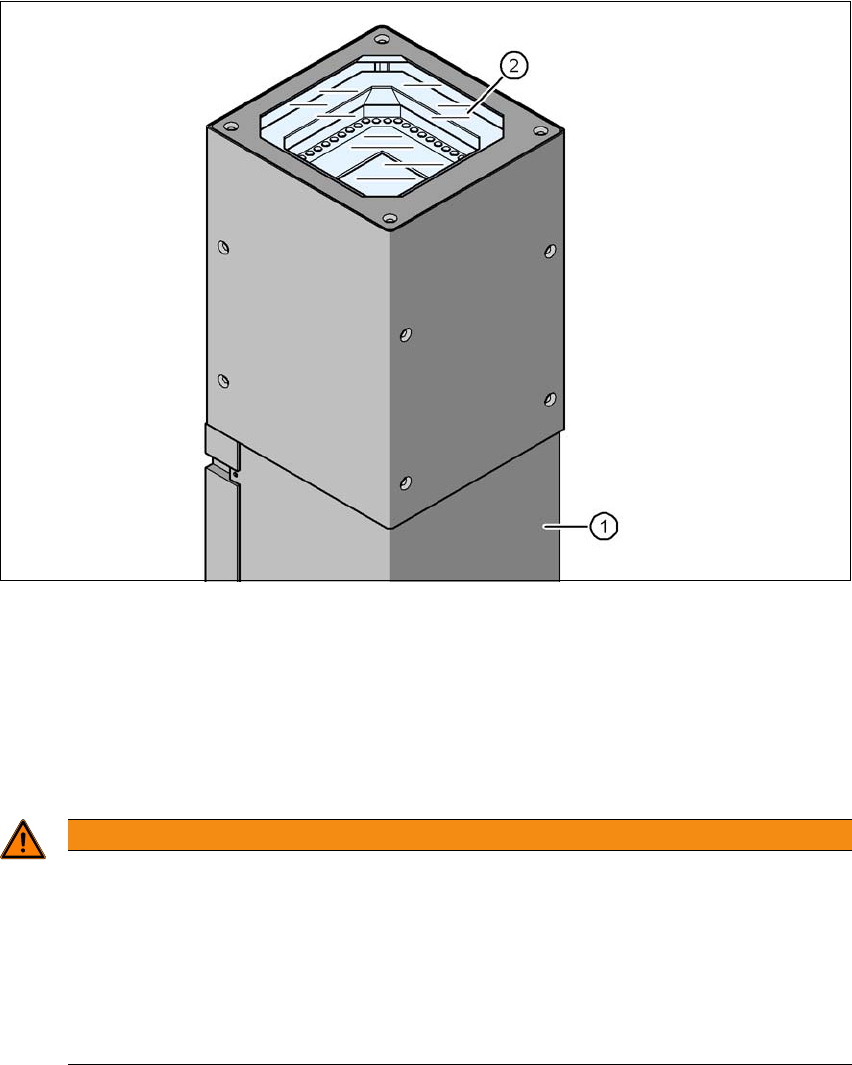
6.11 Component camera for the TwinStar, FC camera
6.11.1 Stationary P&P component camera (type 25) 16 x 16, digital (FC camera)
Item no. 00119718-xx Stationary component camera 16x16 digital, type 25
6
Fig. 6.11 - 1 Stationary P&P component camera (type 25) 16 x 16, digital (FC camera)
(1) Camera housing with integral camera and camera amplifier
(2) Glass plate - illumination and lens levels below
6.11.2 Safety instructions
6
WARNING
Risk of collisions!
When changing the placement head from a TwinStar/VHF to a SpeedStar, the SpeedStar
collides with the camera housing.
Dismantle the stationary component cameras of type 33, 55 x 45, and type 25, 16 x
16 digital (FC camera) for the TwinStar.
When changing the placement head from TwinStar to MultiStar, the stationary compo-
nent camera, type 33, 55 x 45, digital, is fitted in the bottom position.