00197004-04_UM_X-Serie-S_EN.pdf - 第92页
2 Operational safety User manual SIPLACE X-Series 2.6 Safety features From software version 706.1 SP1 Version 10/2014 92 2.6.5.2 Signaling circuit structure The following modules in the signaling circuit are queried indi…
User manual SIPLACE X-Series 2 Operational safety
From software version 706.1 SP1 Version 10/2014 2.6 Safety features
91
2.6.5 EMERGENCY STOP loops and signaling circuit
2.6.5.1 EMERGENCY STOP loop structure
The following contacts are connected in series and form the EMERGENCY STOP loop:
– Make contact elements for the four protective cover switches
– Make contact elements for service flaps (up to 4 service flaps available as an option)
– Normally open (NO) contacts for the two EMERGENCY STOP buttons
– Make contact elements for the four component trolleys
– Channels for the protective contactor combination SSK K6
In addition to analyzing the EMERGENCY STOP loop with the SSK K6, the software also checks
the signaling contacts of the monitored switches. If all contacts are closed (make contact), the soft-
ware sends a digital CAN bus output signal from the I/O control unit to the SSK K6.
2
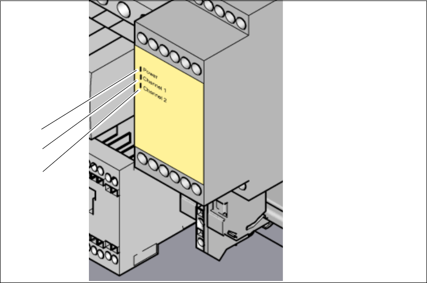
Fig. 2.6 - 9 Signal LED on the protective contactor combination
(1) Mains / Power
(2) Kanal 1 / Channel 1
(3) Kanal 2 / Channel 2
(1)
(2)
(3)
2 Operational safety User manual SIPLACE X-Series
2.6 Safety features From software version 706.1 SP1 Version 10/2014
92
2.6.5.2 Signaling circuit structure
The following modules in the signaling circuit are queried individually:
– The protective cover switches
– Protective switches for service flaps (up to 4 service flaps available as an option)
– Signaling contacts on the component trolley
– EMERGENCY STOP button
All the signaling contacts are closed when the machine is on standby. If a protective cover, for ex-
ample, is raised, the associated signaling contact opens. This status change is signaled to the
control computer via a digital CAN bus input signal from the I/O control unit. An error message to
this effect appears on the user interface.
2.6.5.3 Description of the functions of the EMERGENCY STOP loops
The following conditions must be fulfilled in order to start and operate the machine:
– All component trolleys must be docked in and connected.
– All protective covers must be closed.
– All service flaps must be closed (up to 4 service flaps available as an option).
– Both emergency stop buttons must be released.
– The minimum operating pressure must have been reached.
– The software release ("Control ON") must be enabled, so that the start signal from the "Start"
button can switch on the SSK protective contactor combination.
– 24V- are made available by the output of the AC/DC converter to the start button and the pro-
tective contactor combination (SSK).
If one of the start buttons is now pressed, the protective contactor combination SSK K6 will switch
and the machine will be ready for operation.
User manual SIPLACE X-Series 2 Operational safety
From software version 706.1 SP1 Version 10/2014 2.6 Safety features
93
2
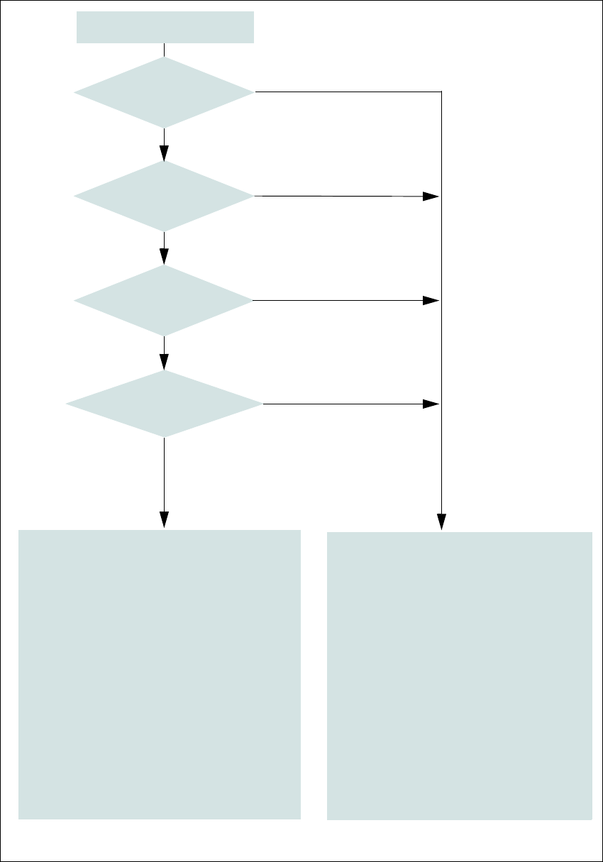
Fig. 2.6 - 10 EMERGENCY STOP loop
Start button pressed
No
No
Yes
No
No
Yes
Yes
2
Active
SSK
a
No
Voltage
Y axis 0 V-
X axis 0 V-
Star axis 0 V-
DP axis 42 V-
Z axis (C&P, TH) 42 V-
Z axis (CPP) 0 V-
Active
PCB conveyor No
Lifting table No
PCB clamping No
Width adjustment No
Tape cutter No
Component trolley feeding device Yes
a) SSK protective contactor combination K3
Yes
Compressed
air min. 0.5 MPa
(5.0 bar)?
EMERGENCY STOP button
pressed?
- Protective cover and/or
service flap open?
Component trolley
EMERGENCY STOP circuit
interrupted?
0
Active
SSK
a
Yes
Voltage
Y axis 260 V-
X axis 260 V-
Star axis 150 V-
DP axis 42 V-
Z axis (C&P, TH) 42 V-
Z axis (CPP) 150 V-
Active
PCB conveyor Yes
Lifting table Yes
PCB clamping Yes
Width adjustment Yes
Tape cutter. Yes
Component trolley feeding device Yes