00197004-04_UM_X-Serie-S_EN.pdf - 第313页
User manual SIPLACE X-Series 5 Working with the machine From software version 706.1 SP1 Version 10/2014 5.11 Observing displays on the X feeder module 313 5.1 1 Observing displays on the X feeder module 5.11.1 Feeder mod…

5 Working with the machine User manual SIPLACE X-Series
5.10 Setting up the feeder modules From software version 706.1 SP1 Version 10/2014
312
5.10.4.5 Splice sensors for X tape feeder modules
Splice sensors can be retrofitted to the X tape feeder modules. There are two versions of the sen-
sor:
Splice sensor for 8 mm and 12 mm X tape feeder modules
Splice sensor for 16 mm to 88 mm X tape feeder modules 5
The splice sensor is installed at the position indicated by item 3 in fig. 5.10 - 8
, page 311.
Tape feeder modules with a splice sensor already installed can also be supplied (see section
3.9.2
, from page 184).
5.10.5 Placing components on the 2x8 mm tape feeder module
The operation and configuration of 2x8 mm feeder modules is described in the "Tape Feeder Mod-
ule
2x8 mm X / Smart Feeder 12 mm X /16 mm X Job Guide".
Item number for German 00196664-xx
Item number for English 00196665-xx
5.10.6 Configuring components on the SIPLACE Smart Feeder
The operation and configuration of the SIPLACE Smart Feeder is described in the "Tape Feeder
Module
2x8 mm X / Smart Feeder 12 mm X /16 mm X Job Guide".
Item number for German 00196664-xx
Item number for English 00196665-xx
User manual SIPLACE X-Series 5 Working with the machine
From software version 706.1 SP1 Version 10/2014 5.11 Observing displays on the X feeder module
313
5.11 Observing displays on the X feeder module
5.11.1 Feeder module with LCD display
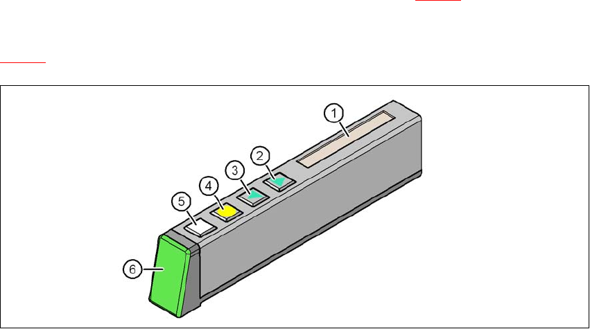
The X feeder modules have a multicolor status display (item 6 in fig. 5.11 - 1) for signaling the op-
erating
statuses and an LCD display (item 1 in fig.
5.11 - 1
).
5
Fig. 5.11 - 1 Buttons, LCD and status displays on the X feeder module
(1) LCD display
(2) FORWARD button
(3) BACK button
(4) FOIL button
(5) SET button
(6) Status display, multicolor
5 Working with the machine User manual SIPLACE X-Series
5.11 Observing displays on the X feeder module From software version 706.1 SP1 Version 10/2014
314
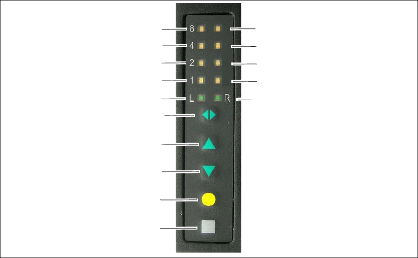
5.11.2 Feeder module with LED display
The SIPLACE SmartFeeder have a multicolored status display for each track and LED display, to
indicate the operating states.
5
Fig. 5.11 - 2 Buttons, LED and status displays: example of SIPLACE SmartFeeder 2x8 mm shown
(1) SET button
(2) FOIL button
(3) BACK button
(4) FORWARD button
(5) Track change button for switching between right and left
(6) LED L left track active
(7) LED 1 mm increment for left track
(8) LED 2 mm increment for left track
(9) LED 4 mm increment for left track
(10) LED 8 mm increment for left track
(11) LED R right track active
(12) LED 1 mm increment for right track
(13) LED 2 mm increment for right track
(14) LED 4 mm increment for right track
(15) LED 8 mm increment for right track
(1)
(2)
(3)
(4)
(5)
(6)
(7)
(8)
(9)
(10)
(15)
(14)
(13)
(12)
(11)