00192662-01.pdf - 第137页
User Manual SIPLAC E F5/F5 HM 3 Introduction and Basic Concepts Software version SR.407.xx 01/2001 US Edition 3.3 User Interf ace - Views and Menus 137 3.3.2.2 "View" Menu The "View" m enu contains t …
3 Introduction and Basic Concepts User Manual SIPLACE F5/F5 HM
3.3 User Interface - Views and Menus Software version SR.407.xx 01/2001 US Edition
136
Switch to operating system ... 3
You use this menu item to switch to the Windows operating system after entering your password.
From here, you can then subsequently return to the SIPLACE user interface. 3
NOTE
This menu option is not available at the "Operator" access level. 3
Å Click the menu item Switch to operating system ...
The Windows user interface is displayed and the SC software continues to run in the back-
ground.
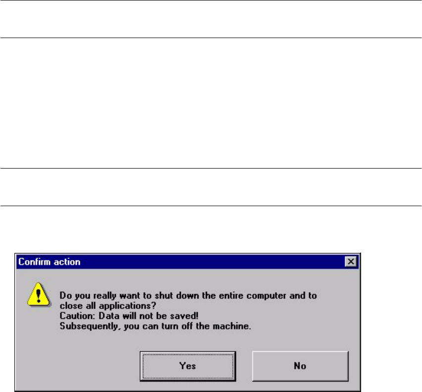
Shut down computer... 3
All applications are closed without any files which may have been processed being saved and the
station computer is shut down. 3
NOTE
This menu option is not available at the "Operator" access level. 3
Å Click the menu item Shut down computer...
The following dialog box is opened.
Å Click Yes if you want to terminate your work.
The station computer is shut down.
Å Switch off the machine at the main switch.
User Manual SIPLACE F5/F5 HM 3 Introduction and Basic Concepts
Software version SR.407.xx 01/2001 US Edition 3.3 User Interface - Views and Menus
137
3.3.2.2 "View" Menu
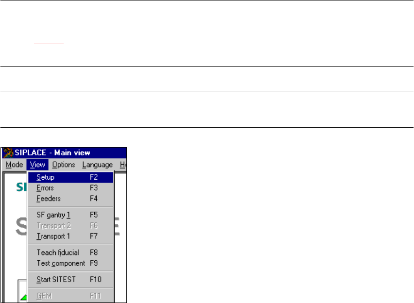
The "View" menu contains the options for calling the placement functions, single functions and vi-
sion functions. It is also used to start the SITEST test program and call the view for running the
GEM functions. 3
Å Click the required menu option.
The screen display is switched to the corresponding view in which you can then call the nec-
essary functions.
NOTE
All the options in this menu can also be called by clicking the corresponding toolbar button (see
section 3.2.2.2
) or by pressing the corresponding function key. If shortcuts have been defined,
these can also be used. 3
NOTE
The 3 menu options below belong to the group of placement functions. 3
3

3 Introduction and Basic Concepts User Manual SIPLACE F5/F5 HM
3.3 User Interface - Views and Menus Software version SR.407.xx 01/2001 US Edition
138
Setup F2 3
The setup for a feeder location is displayed in tabular form. It can be called separately for each of
the four locations.
The procedure is described in more detail in Chapter 4
Placement Functions. 3
Errors F3 3
Errors are differentiated by type and each error type is presented in a separate table. You can call
separate tables for track errors, conveyor errors, machine errors and general errors.
The last error to have occurred is always displayed at the top of the table. Identical errors are cu-
mulated in the error counter ("#E" column).
The procedure is described in more detail in Chapter 4
Placement Functions. 3
Feeders F4 3
Here you can use a variety of functions to display and fill empty tracks for linear feeders or to dis-
play and modify inventory levels for trays and wafflepack changers.
The procedure is described in more detail in Chapter 4
Placement Functions. 3
NOTE
The following 6 menu options belong to the group of single functions.
The single functions are used to execute specific actions following fatal errors as well as to set up
and test the machine since they allow you to address the various functional modules in a defined
manner.
Execution of the single functions is described in Chapter 5 Single Functions. 3
Gantry 1 F5 3
This allows you to call the Single functions for the gantry. These functions can be used, for exam-
ple, to test the Collect&Place head functions. 3
Transport 2 F6 3
Single functions for PCB conveyor 2 (= left conveyor track in the case of twin conveyors) 3
NOTE
The single functions for Conveyor 2 cannot be called unless twin conveyors are configured.
The functions are identical to the functions for Conveyor 1. 3