00192662-01.pdf - 第506页
11 Station extensions /Hardware User Manua l SIPLACE F5/F5 HM 11.5 Ceramic substrate centering Software version SR.407.xx 01/2001 US E dition 506 Fiducial s tructure 11 Recommenda tion 1 Fiduci al stru cture Black res is…

User Manual SIPLACE F5/F5 HM 11 Station extensions /Hardware
Software version SR.407.xx 01/2001 US Edition 11.5 Ceramic substrate centering
505
PLEASE NOTE
Oblique lighting can only be used on the “sub-gantry camera”. 11
11.5.5.2 Fiducial mark recommendation for ceramic substrates
The contrast between the carrier package material and the circuit-board conductor layer is gener-
ally very small with ceramic substrates. The fiducials must therefore be selected with regard to
certain criteria concerning the fiducial shape and structure. Recommended fiducial shapes and
structures are given below. 11
Fiducial shape 11
We recommend a rectangle or square with an edge length of > 1 mm, and a clearance
of > 0.5 mm. 11
11
Fig. 11.5 - 4 Recommended fiducial shape
PLEASE NOTE
Single crosses are also suitable, but they take up more space. 11
0.5 mm
1.0 mm

11 Station extensions /Hardware User Manual SIPLACE F5/F5 HM
11.5 Ceramic substrate centering Software version SR.407.xx 01/2001 US Edition
506
Fiducial structure 11
Recommendation 1
Fiducial structure Black resistive paste as the background, with conductive paste printed on it as
the fiducial.
Recommendation Background 0.75 mm larger than the fiducial on all sides.
Method of illumination Normal light
Advantage Good contrast, good sharpness;
Reference Circuit-board conductor layer
Assessment This combination gives the best results. Highly recommended.
Recommendation 2
Fiducial structure Fiducial made from circuit-board conductor material, e.g. 6119, and overprinted
with passivated glass 4330.
Method of illumination Oblique light
Advantage No additional steps required
Reference Circuit-board conductor layer
Assessment Fiducials are less sharp than for recommendation 1. Recommended.
Recommendation 3
Fiducial structure Fiducials made from circuit-board conductor layer against a free ceramic back-
ground.
Method of illumination Oblique or normal light (depending on the paste)
Advantage No additional steps required
Reference Circuit-board conductor layer
Note Fiducials are less sharp than for recommendation 2.
The fiducial image depends on the surrounding free surface. It may be neces-
sary to teach every circuit separately.
Assessment Recommended under certain conditions.
User Manual SIPLACE F5/F5 HM 11 Station extensions /Hardware
Software version SR.407.xx 01/2001 US Edition 11.5 Ceramic substrate centering
507
11.5.6 Optical centering with the multicolor PCB camera
11.5.6.1 General
As an option, a multicolor PCB camera can be installed in place of the sub-gantry camera. The
multicolor PCB camera offers four different types of illumination. This greatly increases fiducial
recognition, and thus centering accuracy.
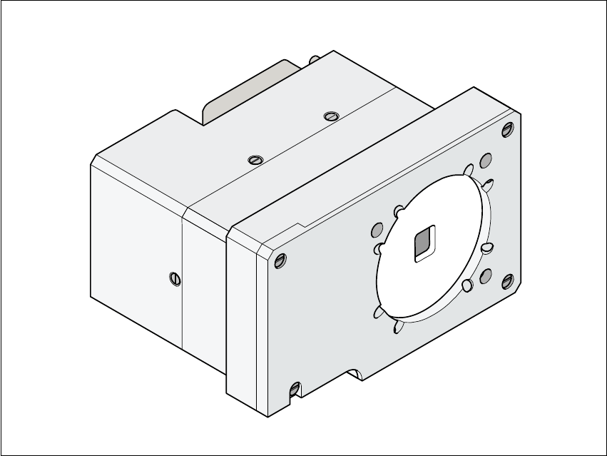
Fig. 11.5 - 5 Multicolor PCB camera
11.5.6.2 Types of illumination for the multicolor PCB camera
The following types of illumination can be selected on the multicolor PCB camera.
– Standard lighting
This mixture of white and infrared lighting can be used to detect a broad range of fiducials. The
image contrast can be improved by varying the illumination, thus optimizing the centering of
different fiducials.
– White lighting
This type of illumination is used for standard PCBs with tinned fiducials.
– Blue oblique lighting
In most cases, this can be used to greatly improve the contrast with bright fiducials on a light