00192662-01.pdf - 第466页
10 Component handling User Manual SIPLACE F5/F5 HM 10.7 Wafflepack Ch anger Software version S R.407.xx 01/2001 US Edition 466 10.7.3.1 Functional Sequence Requirements 10 Flatpack maga zines with the c orrespon ding c o…
User Manual SIPLACE F5/F5 HM 10 Component handling
Software version SR.407.xx 01/2001 US Edition 10.7 Wafflepack Changer
465
10.7.3 Principle of the Wafflepack Changer
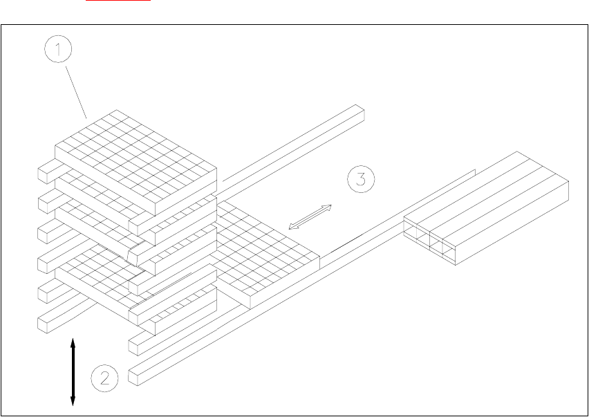
With the wafflepack changer on the SIPLACE F it is possible to hold up to 28 wafflepack maga-
zines and to change these fully automatically. The trays (level) for the wafflepack magazines are
numbered in sequence from bottom to top, with the lowest number at the bottom (1 - 28).
The magazine storage unit travels vertically until the level selected lies with in the travel range of
the horizontal axis. The horizontal axis then removes the tray from the level and transfers it into
the access area of the placement head.
The following Fig. 10.7.2
shows the basic principle behind the wafflepack changer.
Fig. 10.7.2 Principle of the wafflepack changer
(1) Magazine storage unit
(2) Lift
(3) Horizontal axis
10 Component handling User Manual SIPLACE F5/F5 HM
10.7 Wafflepack Changer Software version SR.407.xx 01/2001 US Edition
466
10.7.3.1 Functional Sequence
Requirements 10
Flatpack magazines with the corresponding components are defined in the set-up.
After set-up conversion the magazine storage unit will make a reference run.
The PCB camera approaches the fiducials which are marked on a strip (see Fig. 10.7.2
). 10
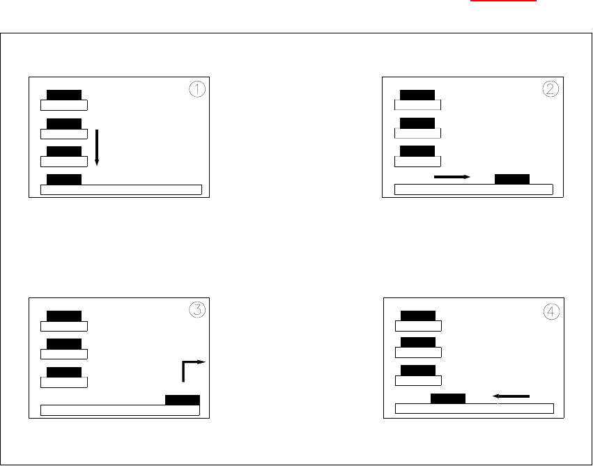
Fig. 10.7 - 3 Functional sequence
10
(1) The selected level of the magazine storage unit is positioned on the feeder axis (horizontal).
(2) The tray is transferred to the access area of the placement head.
(3) The components are removed.
(4) The tray is returned again.
10
– The lift in the magazine storage unit brings the tray from the selected level into position on the
horizontal feeder axis.
– The tray with the flatpack magazine is brought into the placement head's access area.
– Once the desired components have been removed by the placement head, the magazine is
User Manual SIPLACE F5/F5 HM 10 Component handling
Software version SR.407.xx 01/2001 US Edition 10.7 Wafflepack Changer
467
returned in the reverse sequence of operations.
NOTE
If the placement sequence is interrupted with the wafflepack changer being switched off, the set-
up and the current fill level will remain saved in memory. 10
– If the placement sequence is restarted using the set-up which was being used when the se-
quence was aborted, the placement machine will be able to pick up the next component from
the point where it picked up the previous one.
– The position of the trays in the flatpack magazine storage unit and the components they are
filled with is added to the set-up. The wafflepack changer is defined as Location 1. In this con-
nection see UNIX line computer user manual, under 'Station editor'.
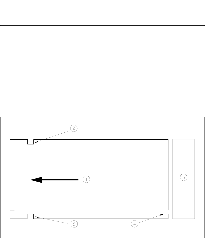
10.7.4 Inserting the Trays
The trays are monitored to make sure they are in the correct position in the magazine storage 10
Fig. 10.7.4 Position of the trays - viewed from the top
(1) Transport direction
(2) Driver notch
(3) Magazine storage unit
(4) Check notch
(5) Driver notch