00192662-01.pdf - 第31页
User Manual SIPLACE F5/F 5 HM 1 Introduction and technical data Software version SR.407.xx 01/2001 US Edition 1.5 Machine description 31 1.5 Machin e desc ription 1.5.1 Functional description of the SIPLACE F5 1 Fig. 1.5…

1 Introduction and technical data User Manual SIPLACE F5/F5 HM
1.4 Revision index Software version SR.407.xx 01/2001 US Edition
30
1.4 Revision index
1
1.4.1 Revisions since 01/2001 edition
1
Instructions Software version Issue
First version User manual 406 02/2000
Revision of User manual 407 01/2001 US
New or modified Chapter / Section
Warning signs on the placement system 2.1.5
Additional warning signs for the NAFTA region 2.1.6
Safety instructions for processing capacitors based on powdered metal 2.1.15
Feeders 10.1.1
Safety instructions for processing capacitors based on powdered metal 10.1.2
12 mm S module for capacitors based on powdered metal, model C/D 10.2.5
12 mm S module for capacitors based on powdered metal, model E 10.2.6
Optical centering with the multicolor PCB camera 11.5.6
Fine calibration 11.13
User Manual SIPLACE F5/F5 HM 1 Introduction and technical data
Software version SR.407.xx 01/2001 US Edition 1.5 Machine description
31
1.5 Machine description
1.5.1 Functional description of the SIPLACE F5
1
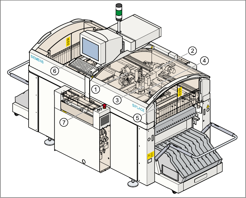
Fig. 1.5 - 1 General view of the F
5
placement machine
(1) 6-segment Collect&Place head with component vision module
(2) Gantry with PCB vision module
(3) Pick&Place head
(4) Fine-pitch vision module for the Pick&Place head
(5) Stationary component supply (location 1)
(6) Stationary component supply (location 3)
(7) PCB conveyor ( dual conveyor option)
1 Introduction and technical data User Manual SIPLACE F5/F5 HM
1.5 Machine description Software version SR.407.xx 01/2001 US Edition
32
The F5 placement machine is a high-speed placement machine with a gantry axis system. The
gantry supports: 1
– a PCB vision module,
– a star-shaped 6-segment Collect&Place head, and
– a Pick&Place head.
The 6-segment Collect&Place head will increase the placement rate if the proportion of ICs in the
placement process is very high. 1
The Pick&Place head is particularly suitable for inserting fine-pitch components. In addition to the
vision module for PCB centering, the F5 machine also has component vision modules for the Col-
lect&Place head and Pick&Place head. 1
A coplanarity laser module and a flip-chip vision module can also be retrofitted as options. 1
A wafflepack changer can be used to supply components. 1
The placement heads pick up components from stationary feeders and then place them in the
PCBs clamped on the PCB conveyor. 1