00192662-01.pdf - 第551页
User Manual SIPLAC E F5/F5 HM 11 Station extensions /Hardware Software version SR.407.xx 01/2001 US Edition 11.13 Fine calibration 551 1 1 .13 Fine calibratio n 1 1.13.1 Overview Fine cali bration invol ves mea suring t …
11 Station extensions /Hardware User Manual SIPLACE F5/F5 HM
11.12 Nozzle changer for the 6-segment Collect&Place head Software version SR.407.xx 01/2001 US Edition
550
11.12.6 Changing the magazine
Å To remove the magazine, push the spring hook (item 1 in Fig. 11.12 - 4) to one side and lift the
magazine (item 1 in Fig. 11.12 - 4
) out of the tray.
11
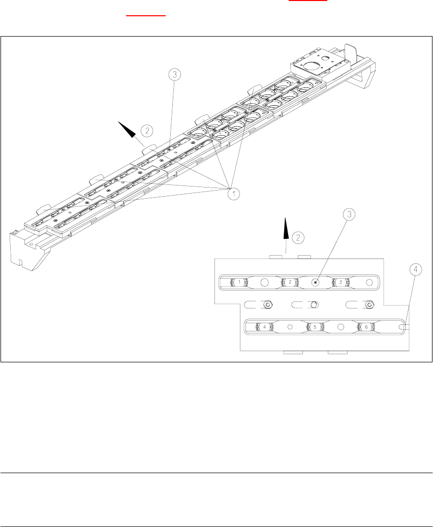
Fig. 11.12 - 4 Changing the magazine
(1) Spring hook
(2) Push the spring hook to one side
(3) Position fiducial
(4) Latching groove
PLEASE NOTE
When you insert the magazine, make sure that the side with the position fiducial points towards
the spring hook. There is a latching groove on the opposite side of the magazine. 11
Å To insert the magazine, place the side with the groove on the tray.
Å Push the spring hook to one side and click the entire magazine onto the tray. Release the
spring hook.
The hook must latch into place.

User Manual SIPLACE F5/F5 HM 11 Station extensions /Hardware
Software version SR.407.xx 01/2001 US Edition 11.13 Fine calibration
551
11.13 Fine calibration
11.13.1 Overview
Fine calibration involves measuring the machine’s placement offset and determining the required
correction from this value. The ‘Fine calibration’ measuring program is integrated into the SITEST
program, and a detailed description of the measuring procedure is given in the ‘Fine calibration’
instructions (article no. 00191655-01). 11
CAUTION
The SITEST program is password-protected. It must only be called up and used by Siemens en-
gineers or appropriately trained personnel. 11
11.13.2 System requirements
The following system requirements must be fulfilled in order to use the fine calibration program:11
Machine type F5, F5 HM
Station computer software version 406.xx or later
SITEST version 406.xx or later
11.13.3 Measuring equipment and tools
The following are supplied as standard: 11
– Mapping plate (glass plate in a metal frame)
– Double-sided transparent adhesive film
– Lighting unit
– Magazine with glass components for the collect&place head and pick&place head with fine-
pitch vision module.
11
The following items must be ordered: 11
– Manual tray (waffle tray holder) to hold the magazine for the glass components
(article number 00116430-xx)
11
11
11 Station extensions /Hardware User Manual SIPLACE F5/F5 HM
11.13 Fine calibration Software version SR.407.xx 01/2001 US Edition
552
The following parts may be ordered if required: 11
– Magazine with glass components for the collect&place head and pick&place head with flip-chip
vision module (article number 00343704-xx)
11.13.4 Functional description
First select the placement program for fine calibration by selecting the ‘Cluster for fine calibration’
option from the ‘Options’ pull-down menu. Then process the mapping plate with the glass compo-
nents from a magazine on the manual tray. 11
After placement, start the SITEST program and start the ‘Fine calibration’ measuring program.
The placement head (collect&place head or pick&place head) will measure the current placement
positions of the glass components and compare these positions with the circular fiducials on the
mapping plate. The results are used to calculate the offset values. 11
The offset values are used to determine corrected values, which are then entered in the machine’s
machine data. 11
11
11