00192662-01.pdf - 第519页
User Manual SIPLAC E F5/F5 HM 11 Station extensions /Hardware Software version SR.407.xx 01/2001 US Edition 11. 8 Coplanarity laser module 519 Fig. 1 1.8 - 4 O verview of the coplanarity laser m odule (1) Green LED: 5V o…
11 Station extensions /Hardware User Manual SIPLACE F5/F5 HM
11.8 Coplanarity laser module Software version SR.407.xx 01/2001 US Edition
518
DANGER
The safety guarantee is automatically invalidated if safety devices are modified or bypassed.
The user must also conform to the guidelines issued by the umbrella organization of employers’
liability insurance associations – VBG 93 – i.e.:
- Registration with the employers’ liability insurance association
- Appointment of a laser protection officer
Drawing up guidelines for use of the module 11
11.8.4 Overview
11.8.4.1 Vision analysis unit
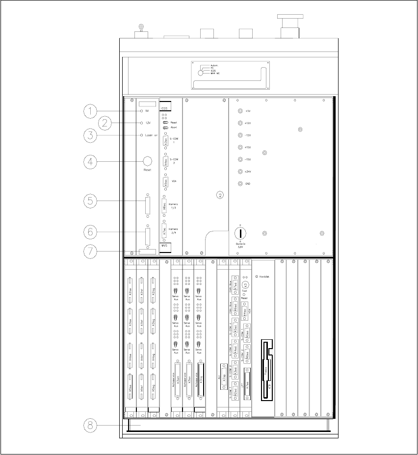
The coplanarity laser module consists of two components: the vision analysis unit with its control
section, and the laser module. The vision analysis unit is located in the control unit (see Fig. 11.8
- 4). The operating state is indicated by three green LEDs on the front panel of the vision analysis
unit. 11
Press the RESET key to initialize the coplanarity laser module. 11
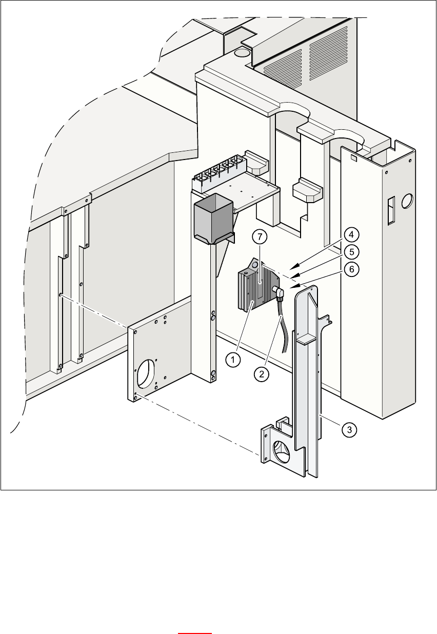
11.8.4.2 Laser module
The laser module is fixed to a supporting frame on the right-hand side of the machine (see Fig.
11.8 - 5
).
Two red LEDs and one green LED signal the operating states of the laser module. 11
11
LED (see 11.8 - 4)On Off
1 green 5V operating voltage No voltage
2 green 12V operating voltage No voltage
3 green Laser module in use Laser module switched off
LED (see Fig. 11.8 - 5)On Off
4 red OUT OF RANGE
(outside the measuring range)
–
5 red POOR TARGET
(component is insufficiently reflective)
–
6 green Laser module in use Laser module switched off
User Manual SIPLACE F5/F5 HM 11 Station extensions /Hardware
Software version SR.407.xx 01/2001 US Edition 11.8 Coplanarity laser module
519
Fig. 11.8 - 4 Overview of the coplanarity laser module
(1) Green LED: 5V operating voltage
(2) Green LED: 12V operating voltage
(3) Green LED: Laser module switched on
(4) RESET key
(5) SUB-D connector, 9-pin, COM2: to the machine controller
(6) SUB-D connector, 15-pin: to the laser module
(7) Vision analysis unit with control section
(8) Control unit
11 Station extensions /Hardware User Manual SIPLACE F5/F5 HM
11.8 Coplanarity laser module Software version SR.407.xx 01/2001 US Edition
520
Fig. 11.8 - 5 Coplanarity laser module
(1) Laser module
(2) Connecting cable
(3) Supporting frame
(4) Red LED: OUT OF RANGE
(5) Red LED: POOR TARGET
(6) Green LED: LASER ON
(7) Class 3 B Laser Product, see Fig. 11.8 - 2