00192662-01.pdf - 第98页
2 Operational Safety User Manual SIPLACE F5/F5 HM 2.2 Safety equipment Software version SR. 407.xx 01/2001 US E dition 98 2.2 Safety equipme nt 2.2.1 Prot ective co vers 2 Fig. 2.2 - 1 SIPLACE safety equipment Key to Fig…
User Manual SIPLACE F5/F5 HM 2 Operational Safety
Software version SR.407.xx 01/2001 US Edition 2.1 Safety instructions
97
2.1.15 Safety instructions for processing capacitors based on powdered metal
There is a risk associated with processing capacitors based on powdered metal (e.g. tantalum). 2
The risk is that 2
– An exothermic reaction, i.e. a sudden build-up of heat, may occur if these components are
damaged. If the ambient conditions are unfavorable, and depending on the capacitance, this
build-up of heat can cause damage.
– This effect can occur when these components are cut.
Please contact your suppliers to clarify whether the components that you handle are affected. 2
In extremely rare cases, this risk can occur in the tape cutter of SIPLACE machines, with the re-
mote possibility of causing a smoldering fire in the waste tape. 2
The ambient conditions are unfavorable if: 2
(1) The components remain on the tape while the set tape cycle is checked (since the operator
can cycle the feeder onward without removing components during this check).
(2) The components remain on the tape, e.g. due to a tear in the cover foil.
(3) The components remain on the tape, and the components or tape do not conform to the
specification, thus increasing the pick-up error rate.
Please follow the instructions given below to minimize the risk when placing capacitors based on
powdered metal. 2
(1) If the component tape is cycled onward manually, the operator must remove any components
remaining in the tape pocket.
(2) If the cover foil tears, the operator must remove any components remaining on the tape.
(3) The waste tape container must be emptied regularly (recommended interval: every hour).
2
CAUTION
To avoid the risk, it is essential to use only feeders that have
been approved for placing such components, namely:
Article no.: 00141117-01 Model E
Article no.: 00141118-01 Model C/D 2
2
The feeders are labeled as shown
below:
2
Approved for
capacitors based on
metal-powder
Freigegeben für
Kondensatoren auf
Metallpulver-Basis
2 Operational Safety User Manual SIPLACE F5/F5 HM
2.2 Safety equipment Software version SR.407.xx 01/2001 US Edition
98
2.2 Safety equipment
2.2.1 Protective covers
2
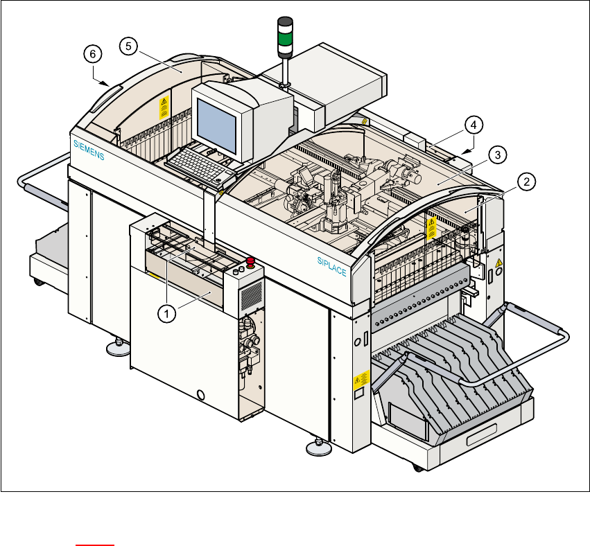
Fig. 2.2 - 1 SIPLACE safety equipment
Key to Fig. 2.2 - 1
(1) Cover and guard on the input belt
(2) Safety panels, righthand side
(3) Protective cover
(4) Cover and guard on the output conveyor
(5) Protective cover
(6) Safety panels, lefthand side
User Manual SIPLACE F5/F5 HM 2 Operational Safety
Software version SR.407.xx 01/2001 US Edition 2.2 Safety equipment
99
2.2.1.1 General
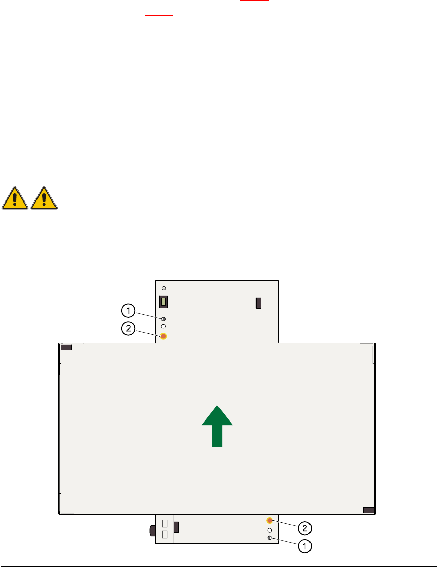
The gantry positioning range is covered by two protective covers. If you want to open the protec-
tive covers, first press the Stop button (item 1 in Fig. 2.2 - 2
) or the emergency stop mushroom-
head push-button (item 2 in Fig. 2.2 - 2
). The power to the gantry axes will be switched off and the
gantries will stop immediately. 2
If you open one of the protective covers or a guard on the incoming or outgoing conveyor, the
power to the gantry axes will be switched off and they will stop immediately. 2
If the key switch is closed (position I), you can continue to pace the star at reduced speed while
the protective covers are open. 2
Placement will stop if you press the emergency stop button. You can then either cancel or continue
placement of the PCB. The protective covers at the sides can be opened in order to refill with com-
ponents when the machine has stopped. 2
WARNING
The protective covers must only be opened, with the key switch closed (position I), by appropri-
ately qualified and trained personnel. 2
Fig. 2.2 - 2 Stop and emergency stop mushroom-head push-buttons
(1)Stop button(2) EMERGENCY-STOP mushroom-head push-button 2