00192662-01.pdf - 第53页
User Manual SIPLACE F5/F 5 HM 1 Introduction and technical data Software version SR.407.xx 01/2001 US Edition 1.12 Overview of the modules - gantry 53 1.12 Over view of the m odules - gan try 1.12.1 Position of the gant …
1 Introduction and technical data User Manual SIPLACE F5/F5 HM
1.11 Overview of the modules - controls Software version SR.407.xx 01/2001 US Edition
52
1.11.4 Technical data – component barcode reader
1
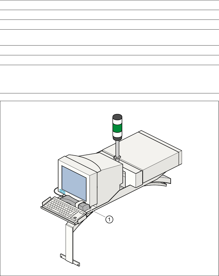
Fig. 1.11 - 2 Component barcode reader
(1) Component barcode reader
Connected to Station computer
Data entry Via barcode scanner or keyboard
Number of characters Up to 40
Not permissible Barcodes starting with a 1 or 2
and less than 5 characters long
Number of barcodes Up to 6 per component
Filter for suppressing data Up to 1 per barcode
Preset code types Code 39 (standard or ASCII)
Code 2 of 5, interleaved and normal,
Code 128, UPC/EAN/JAN codes
(others available upon request)
User Manual SIPLACE F5/F5 HM 1 Introduction and technical data
Software version SR.407.xx 01/2001 US Edition 1.12 Overview of the modules - gantry
53
1.12 Overview of the modules - gantry
1.12.1 Position of the gantry
1
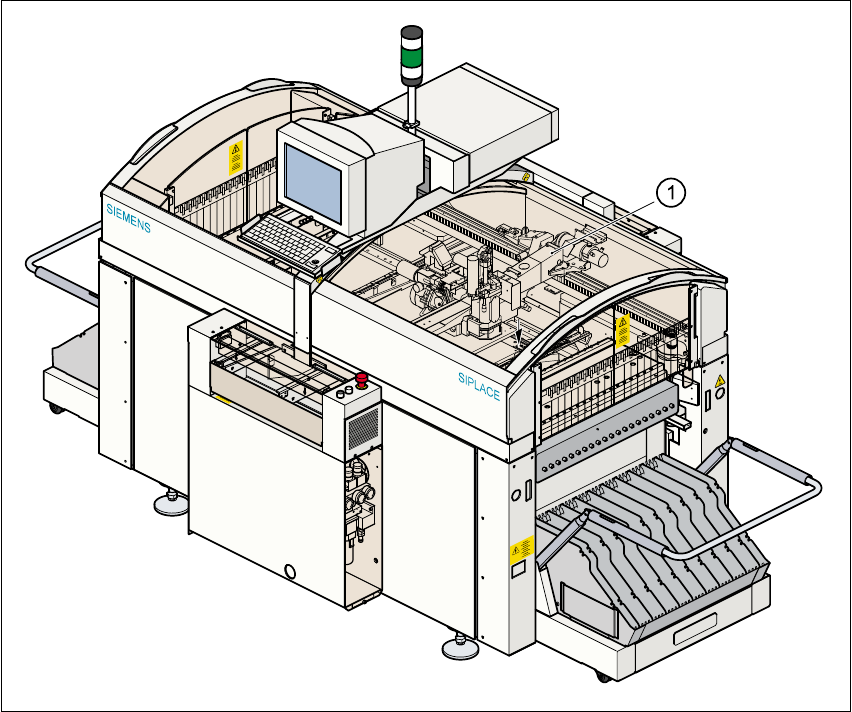
Fig. 1.12 - 1 Position of the gantry
(1) Gantry
1
The gantry system consists of two functional groups 1
– X axis and
– Y axis.
1
1 Introduction and technical data User Manual SIPLACE F5/F5 HM
1.12 Overview of the modules - gantry Software version SR.407.xx 01/2001 US Edition
54
1.12.2 Structure of the X axis
1
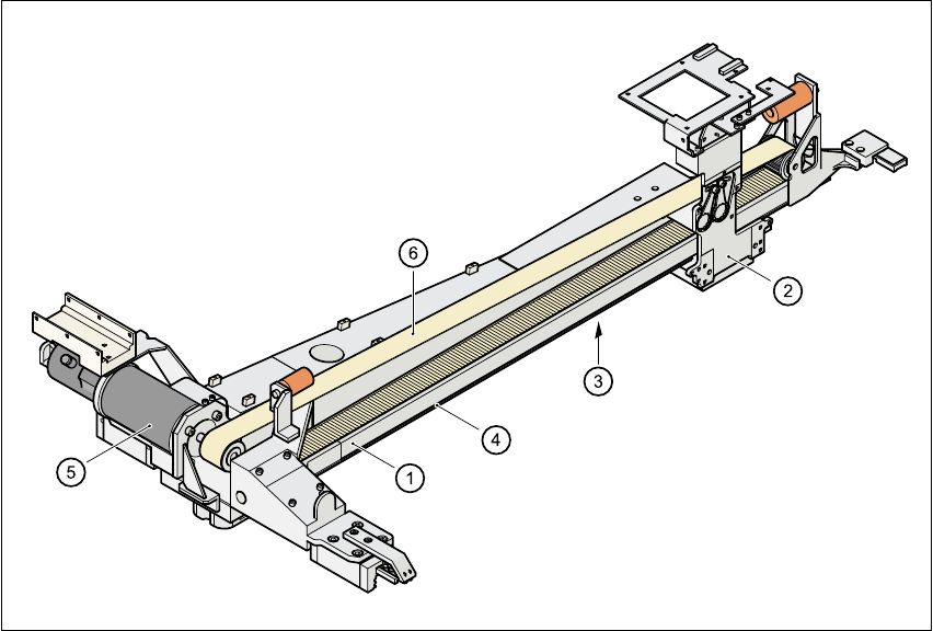
Fig. 1.12 - 2 Structure of the X axis
The x axis essentially consists of the following main modules: 1
– Gantry arm (1)
– Head mount (2)
– X axis measuring system (3)
– X axis guide system (4)
– X axis three-phase AC servomotor (5) (F
5
HM), X axis DC servomotor (F
5
)
– Toothed belt (6)
The head mount holds the following components: 1
– Sub-gantry camera (camera for the PCB vision module)
– Head board
– Measuring head for the x axis measuring system
– Revolver head