00192662-01.pdf - 第246页
6 Vision functions User Manua l SIPLACE F5/F5 HM 6.3 Component v ision systems Software version SR. 407.xx 01/2001 US E dition 246 provide informa tion o n dev iation s in po sitio n, the rotational angle, lead conditio …

User Manual SIPLACE F5/F5 HM 6 Vision functions
Software version SR.407.xx 01/2001 US Edition 6.3 Component vision systems
245
6.3.3.2 Technical data
Fine-pitch vision module for the Pick&Place head 6
Camera type: SONY XC77
Number of pixels: 484 x 484
Field of view: 38 mm x 38 mm
Illumination method: Front lighting (infrared light)
3 illumination levels
Image processing: HALE gray scale method
(H
igh Accuracy Lead Extraction)
Screen: RGB monitor (VGA mode), 640 x 484 pixels
Range of recognizable components: Fine-pitch up to 55 mm x 55 mm and BGAs
(ball grid arrays)
Minimum lead pitch: 0.4 mm
Flip-chip vision module for the Pick&Place head 6
Camera type: SONY XC75C
Number of pixels: 484 x 484
Field of view: 12.2 mm x 9.2 mm
Illumination method: Front lighting (infrared light)
2 illumination levels
Image processing: approx. 1 second for standard flip-chips
Screen: RGB monitor (VGA mode), 640 x 484 pixels
Range of recognizable components: flip-chips and fine-pitch components up to 15 mm x
15 mm
Minimum ball size: 80 µm
Minimum lead pitch: 0.2 mm
6.3.3.3 Functional description
There are two optical centering systems available for centering components with the Pick&Place
head: 6
– the fine-pitch vision module for fine-pitch components up to 55 mm x 55 mm in size, and with
a minimum lead pitch of 0.4 mm, and BGAs (ball grid arrays)
– the flip-chip vision module for flip-chips and fine-pitch components up to 15 mm x 15 mm in
size, and with a minimum lead pitch of 0.2 mm
The Pick&Place head picks up components from waffle pack trays, and positions them over the
optical centering system used. Offset rows of LEDs evenly illuminate the component with infrared
light. The digital image of the component generated by the camera is then transferred to the vision
analysis unit, where it is evaluated according to the component type. The results thus obtained
6 Vision functions User Manual SIPLACE F5/F5 HM
6.3 Component vision systems Software version SR.407.xx 01/2001 US Edition
246
provide information on deviations in position, the rotational angle, lead condition, and the mapping
quality of the component. 6
New illumination methods and special algorithms for obtaining the component parameters have
been developed for BGAs and flip-chips. This means that this new generation of components
can now be optically centered.
The IC head returns any components that cannot be optically centered to the waffle pack tray for
further analysis.
6
6
6
6
6.3.4 Criteria for Recognition of Components
Shape of the Components 6
Optical component centering allows both regular and irregular components to be centered. The
maximum number of leads, horizontally and vertically, is 99 in each case. 6
Criteria for regular components 6
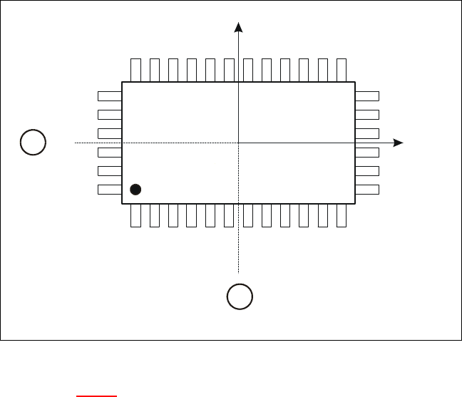
Definition:
A component is deemed to be regular when it satisfies the following four conditions: 6
– rectangular package shapes (special case: square shape)
– only one lead type per side
– only one lead group per side
– opposite lead groups located symmetrically with respect to the two main axes
(X and Y axes).
User Manual SIPLACE F5/F5 HM 6 Vision functions
Software version SR.407.xx 01/2001 US Edition 6.3 Component vision systems
247
6
Fig. 6.3 - 1 Regular component
Key to Fig. 6.3 - 1
(1) Axis of symmetry
6
Criteria for irregular components 6
Definition:
A component is deemed to be irregular when it does not satisfy the conditions for regular compo-
nents. 6
Additional conditions for centering with the component vision module: 6
– In any one row up to 3 different lead types are permitted.
– In any one row up to 15 groups are permitted.
6
Y
X
Pin 1
1
1