00192662-01.pdf - 第510页
11 Station extensions /Hardware User Manua l SIPLACE F5/F5 HM 11.6 Nozzle changer for the Pick&P lace head Software v ersion SR.407.xx 01/2001 US Edition 510 The SIP LACE F machine is eq uipped as standard w ith a n …
User Manual SIPLACE F5/F5 HM 11 Station extensions /Hardware
Software version SR.407.xx 01/2001 US Edition 11.6 Nozzle changer for the Pick&Place head
509
11.6 Nozzle changer for the Pick&Place head
11.6.1 Overview
11
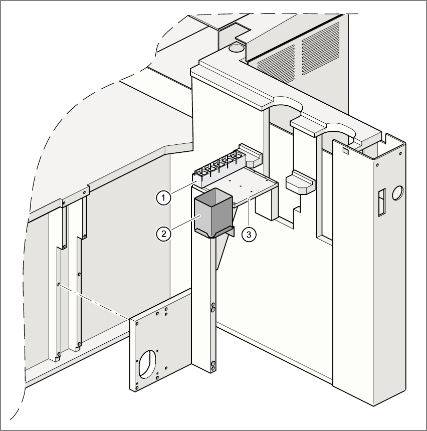
Fig. 11.6 - 1 Mounting position of the nozzle changer for the Pick&Place head
(1) Magazine for 5 nozzles
(2) Reject bin
(3) Mounting plate
11 Station extensions /Hardware User Manual SIPLACE F5/F5 HM
11.6 Nozzle changer for the Pick&Place head Software version SR.407.xx 01/2001 US Edition
510
The SIPLACE F machine is equipped as standard with a nozzle changer for the Pick&Place head.
The scope of delivery includes a nozzle magazine for five nozzles, e.g. four standard nozzles from
the 4xx series, and one special nozzle. Three additional nozzle magazines can be retrofitted, if
required, thus providing up to 20 nozzles. 11
The nozzle magazines (see point 1 in Fig. 11.9 - 8
) are each centered with two parallel pins, and
fixed to the mounting plate with a countersunk bolt (see point 3 in Fig. 11.9 - 8
). Nozzles are ex-
changed automatically during the placement process. 11
11.6.2 Technical data -Nozzle changer for the Pick&Place head
11.6.3 Functional description
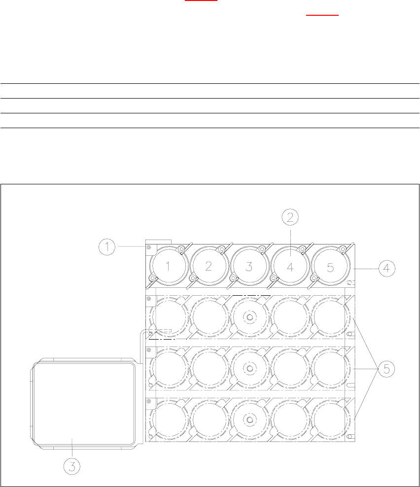
Fig. 11.6 - 2 Overview of the nozzle changer
Nozzle types All nozzles from the 4xx series, special nozzle (optional)
Capacity 1 to 4 magazines each with 5 nozzles, can be configured as required
Nozzle exchange time Approx. 2 seconds per nozzle
User Manual SIPLACE F5/F5 HM 11 Station extensions /Hardware
Software version SR.407.xx 01/2001 US Edition 11.6 Nozzle changer for the Pick&Place head
511
Key to Fig. 11.6 - 2
– All the magazines have a position fiducial (item 1 in Fig. 11.6 - 2) for position recognition pur-
poses.
– The individual magazine locations are numbered consecutively from 1 to 4.
– The individual nozzle holders are numbered consecutively from 1 to 5 in each magazine.
– The nozzles are fixed in place in the holders by sprung hooks. The nozzles are either clamped
or released, depending on the direction of rotation of the Pick&Place head axis.
11.6.4 Notes on operation and maintenance
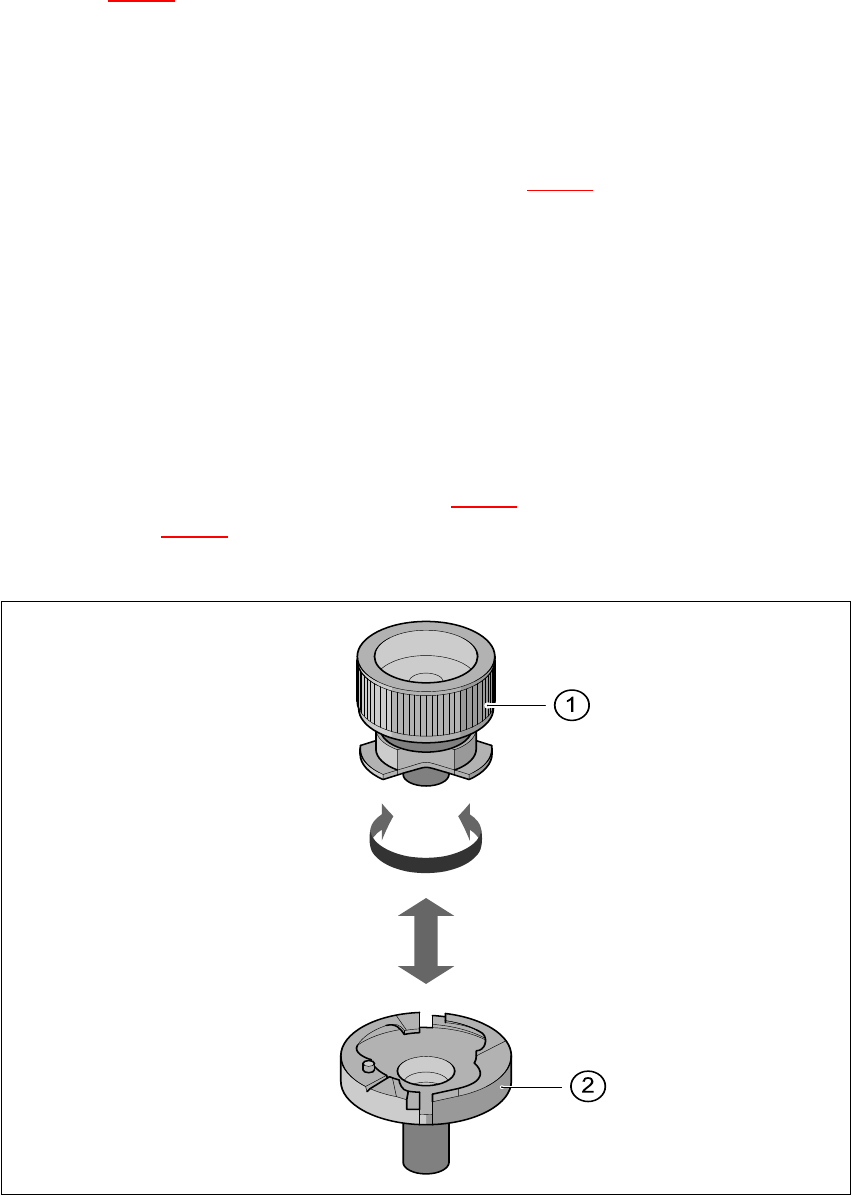
Å Use the nozzle removal tool (see point 1 in Fig. 11.6 - 3) to insert or exchange the nozzles
(point 2 in Fig. 11.6 - 3
).
Å Clean the nozzle changer as described in the maintenance instructions.
Fig. 11.6 - 3 Removing the nozzle from the nozzle changer
(1) Position fiducial (2) Nozzle holder
(3) Reject bin (4) Magazine 1 (standard)
(5) Magazines 2 to 4 (optional) 11