00192662-01.pdf - 第35页
User Manual SIPLACE F5/F 5 HM 1 Introduction and technical data Software version SR.407.xx 01/2001 US Edition 1.5 Machine description 35 1.5.3 T echnical dat a – overvi ew of the SIPL ACE F 5 * The SIPLACE F5 can be equi…
1 Introduction and technical data User Manual SIPLACE F5/F5 HM
1.5 Machine description Software version SR.407.xx 01/2001 US Edition
34
There is a DCA package available for the SIPLACE F
5
placement machine. This contains an al-
ternative vision module that can be installed on the 6-segment Collect&Place head in place of the
conventional vision module. The DCA package optimizes the placement speed and accuracy for
flip-chips and bare dies. 1
The concept behind the placement machine 1
– with its stationary feeders,
– with PCBs that do not move during placement,
– and its positionable placement heads
has number of significant benefits: 1
– For example, the flexible 6-segment Collect&Place head combined with automatic nozzle
changer enables the nozzle configuration to be changed temporarily and automatically
adapted to receive different component sizes You can also optimize the travel paths, and the
placement sequence.
– With stationary feeders, even the tiniest components are picked up reliably.
– The components cannot slip on the PCB during placement (as is often the case with moving
PCBs) since the PCB does not move.
– Sophisticated optical centering systems (vision systems) for components and PCBs also en-
sure high component positioning accuracy.
– Components can be topped up and tapes can be spliced without stopping the machine.
– Prepared component tables enable the placement machine to be retooled without long idle
times.

User Manual SIPLACE F5/F5 HM 1 Introduction and technical data
Software version SR.407.xx 01/2001 US Edition 1.5 Machine description
35
1.5.3 Technical data – overview of the SIPLACE F
5
* The SIPLACE F5 can be equipped to place 0201 components.
(Please contact the factory for details).
** Only applies to the DCA package
*** Only applies to the DCA package and flip-chip vision module for the Pick&Place head
Procedure Pick&place / collect&place
Component range
Standard vision module
DCA vision module
from 0603 to 55mm x 55mm
from 0.5mm x 0.25mm (0201*) to 55mm x 55mm
Max. placement rate
6-segment Collect&Place head
Pick&Place head
8,000 components/hour
1,800 components/hour
6-segment Collect&Place head
Angular accuracy
Placement accuracy
± 0.225°/ 3 σ, ± 0.30°/ 4 σ, ± 0.45°/ 6 σ
± 52.5µm / 3 σ, 70µm / 4 σ, 105µm / 6 σ
± 45µm / 3 σ, 60µm / 4 σ, 90µm / 6 σ) **
Pick&Place head
Angular accuracy
Placement accuracy
± 0.052°/ 3 σ, ± 0.07°/ 4 σ, ± 0.105°/ 6 σ
± 37.5µm / 3 σ, 50µm / 4 σ, 75µm / 6 σ
(± 30µm / 3 σ, 40µm / 4 σ, 60µm / 6 σ) ***
PCB format
50mm x 50mm to 460mm x 460mm
(optionally 460mm x 508mm, 18" x 20")
Feeder capacity 40 locations for feeders
Component supply
Types of feeder
Changeover table, wafflepack changer, manual WPC
trays
Component tapes, stick magazines, bulk cases
Operating system Microsoft Windows NT / RMOS
Connection In-line or stand alone
Space required 4 m² / module
1 Introduction and technical data User Manual SIPLACE F5/F5 HM
1.5 Machine description Software version SR.407.xx 01/2001 US Edition
36
1.5.4 Functional description of the SIPLACE F
5
HM
1
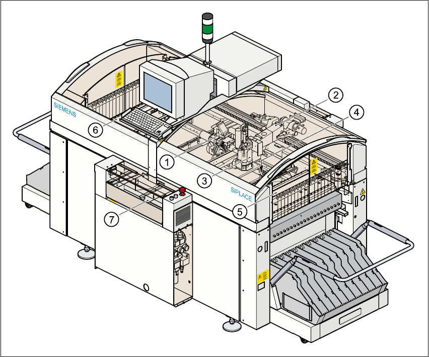
Fig. 1.5 - 3 General view of the F
5
HM placement machine
(1) 6/12-segment Collect&Place head with component vision module
(2) Gantry with PCB vision module
(3) Pick&Place head
(4) Fine-pitch vision module for the Pick&Place head
(5) Stationary component supply (location 1)
(6) Stationary component supply (location 3)
(7) PCB conveyor ( dual conveyor option)
1
1