00192662-01.pdf - 第491页
User Manual SIPLAC E F5/F5 HM 11 Station extensions /Hardware Software version SR.407.xx 01/2001 US Edition 11.3 Dual conveyor 491 1 1.3 Dual conv eyor 1 1 .3.1 Structure of the dual conveyor The co nveyor belts are driv…

11 Station extensions /Hardware User Manual SIPLACE F5/F5 HM
11.2 Component barcode Software version SR.407.xx 01/2001 US Edition
490
11.2.4 Technical data
Connection Station computer
Data entry Via barcode scanner or keyboard
Number of characters Up to 40
Not permissible
Barcode starts with number 1 or 2, and is less than
5 characters long
Number of barcodes Up to 6 per component
Filter for suppressing data Up to 1 per barcode
Preset code types
Code 39 (standard or ASCII)
Code 2 of 5, interleaved and normal
Code 128, UPC/EAN/JAN codes
(others available upon request)
User Manual SIPLACE F5/F5 HM 11 Station extensions /Hardware
Software version SR.407.xx 01/2001 US Edition 11.3 Dual conveyor
491
11.3 Dual conveyor
11.3.1 Structure of the dual conveyor
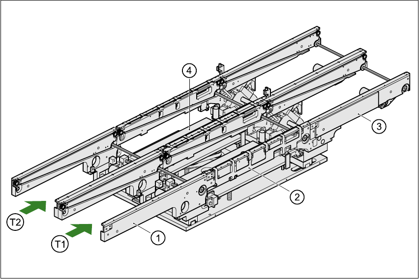
The conveyor belts are driven by DC motors. Each center conveyor has a lifting table for clamping
the PCBs. The width of the PCB conveyor can be adjusted, either using the menu or from the line
computer. 11
11
Fig. 11.3 - 1 Structure of the dual conveyor
11.3.2 General
As the name suggests, the dual conveyor has two tracks. These are independent of one another,
both electrically and mechanically. As standard, the fixed transport side is on the right, although
there is another variant in which the fixed transport side is on the left. 11
(1) Input conveyor (2) Center conveyor
(3) Output conveyor (4) Lifting table
T1 Transport track 1 11 T2 Transport track 2 11

11 Station extensions /Hardware User Manual SIPLACE F5/F5 HM
11.3 Dual conveyor Software version SR.407.xx 01/2001 US Edition
492
The transport type can be set to either “synchronous dual conveyor” or “asynchronous dual con-
veyor”. To do this, enter the transport type in the machine data (CONFIG.MA). 11
11.3.3 Definition of the transport tracks
The right-hand transport track (viewed in the transport direction) is designated “transport 1”, and
the left-hand track as “transport 2” (see Fig. 11.3 - 1
). 11
11.3.4 Changing the transport type
11.3.5 Asynchronous transport type
11.3.6 Description
In asynchronous mode, one PCB is processed on one transport track, while another PCB on the
second transport track is moved into the placement position. This saves the full transport time,
greatly increasing output, particularly for PCBs with a short cycle time. 11
11.3.7 Function
If the machine is supplied with job data (cluster, set-up), at any given time during placement the
PCBs on the input conveyors are transported onto the center conveyor (if it is free). The placement
sequence starts as soon as a PCB has been transported onto the center conveyor concerned. The
PCBs are processed one after another. 11
PLEASE NOTE 11
The components to be placed, and the width of the PCBs on transport tracks 1 and 2 must be iden-
tical. 11
If the placement sequence is interrupted, the transport interface will be disabled, and the PCBs
currently on the center conveyors will be completed. 11
The transport interface is enabled or disabled for both transport tracks at the same time. 11
Transport type Entry in CONFIG.MA
Single conveyor 0
Synchronous dual conveyor 1
Asynchronous dual conveyor 2