00192662-01.pdf - 第58页
1 Introduction and technical data User Manual SIPLACE F5/F5 HM 1.13 Overview o f the modules - placement heads Software version SR. 407.xx 01/2001 US E dition 58 1.13. 4 Struc ture of t he Pick&P lace he ad 1 Fig. 1.…

User Manual SIPLACE F5/F5 HM 1 Introduction and technical data
Software version SR.407.xx 01/2001 US Edition 1.13 Overview of the modules - placement heads
57
– The component vision camera creates an image of the current component.
– The precise position of the component is also determined.
– The package form of the current component is compared against the programmed package
form in order to identify it. Any components that cannot be identified are rejected.
– The turning station turns the component to the required placement angle.
1.13.2 Description of the 12-segment Collect&Place head
– The 12-segment Collect&Place head works using the "Collect & Place" principle, i.e. the com-
ponents are held by the nozzles with the aid of a vacuum and, after one complete pick-up cycle,
are placed gently and accurately on the PCB with the aid of blast air. The vacuum in the noz-
zles is also checked several times to determine whether the components were picked up and
set down correctly.
– The "adaptive" sensor stop mode of the Z-axis compensates for any irregularity of the
PCB-surface when the components are set down.
– Defective components are rejected, and are reworked during a repair cycle.
1.13.3 Technical data of the 12-segment Collect&Place head
Component range 0402 to 18.7mm x 18.7mm including BGA, µBGA,
flip-chip, TSOP, QFP, PLCC, SO to SO32, DRAM
Max. height 6 mm
Min. lead pitch 0.5 mm
Min. dimensions 0.5 mm x 1.0 mm
Max. dimensions 18.7 mm x 18.7 mm
Max. weight 2 g
Max. travel of z axis 16 mm
Programmable placement force 2.4 to 5.0 N
Nozzle types 9xx (F
5
HM), 7xx (F
5
)
Angular accuracy ± 0.525° / 3 σ, ± 0.70° / 4 σ, ± 1.05° / 6 σ
Placement accuracy ± 67.5 µm / 3 σ, ± 90 µm / 4 σ, ± 135 µm / 6 σ
1 Introduction and technical data User Manual SIPLACE F5/F5 HM
1.13 Overview of the modules - placement heads Software version SR.407.xx 01/2001 US Edition
58
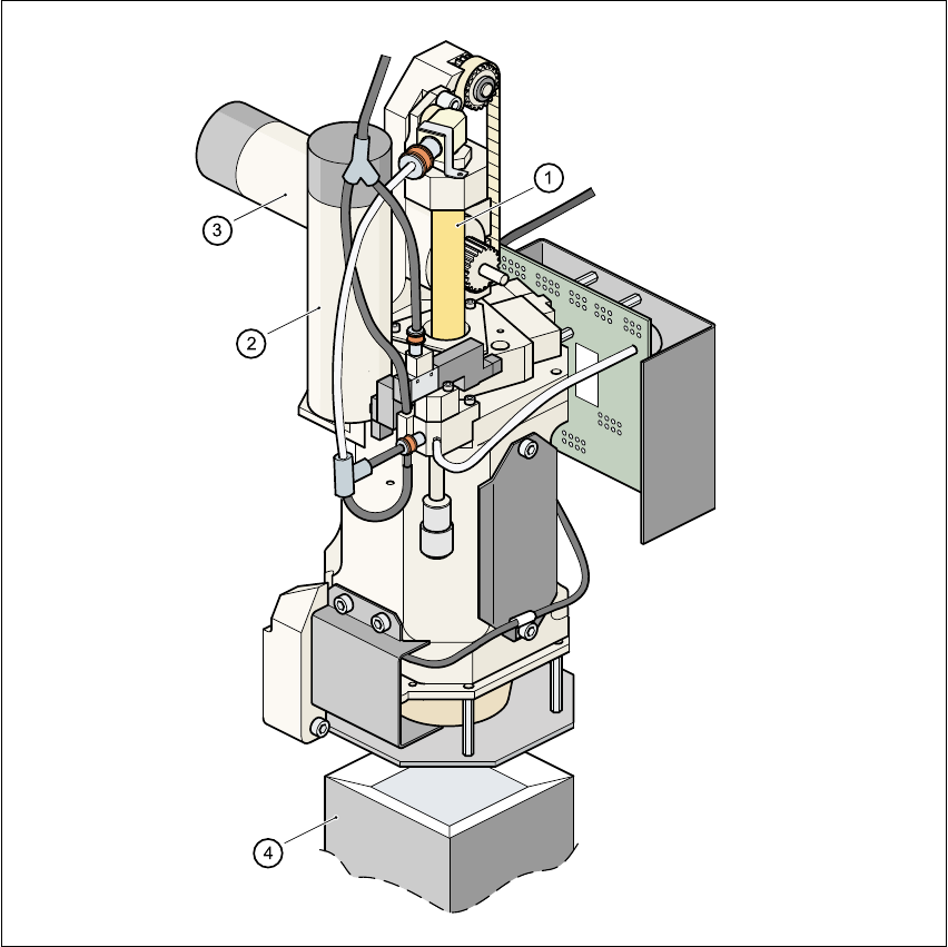
1.13.4 Structure of the Pick&Place head
1
Fig. 1.13 - 2 Structure of the Pick&Place head.
(1) Sleeve
(2) DR axis driving mechanism
(3) Z axis driving mechanism
(4) Fine-pitch vision module

User Manual SIPLACE F5/F5 HM 1 Introduction and technical data
Software version SR.407.xx 01/2001 US Edition 1.13 Overview of the modules - placement heads
59
1.13.5 Description of the Pick&Place head
The Pick&Place head works according to the pick&place principle, which means that a compo-
nent is picked up by the nozzle with the aid of a vacuum. After optical centering with the fine-pitch
or flip-chip vision module, the component is turned to the correct placement angle, and inserted
into the PCB with high precision. The Pick&Place is particularly striking because of its high angu-
lar accuracy. 1
1.13.6 Technical data - Pick&Place head
Component range up to 55mm x 55mm
Max. height
Component height ≤ 13.5mm- PCB thickness
- PCB sagging
Option:
Component height ≤ 20mm- PCB thickness
- PCB sagging
Min. lead pitch 0.4mm (standard), 0.25mm (option)
Max. dimensions
up to 32mm x 32mm with single measurement
up to 55mm x 55mm with quadruple measurement
Max. weight 25 g
Programmable placement
force
1 - 10 N
Nozzle types
4xx, 5 standard nozzles including flip-chip nozzle with nozzle
changer
Component centering
Fine-pitch component vision module (standard)
Flip-chip vision module (option)
Benchmark placement rate 1,800 components/hour
D axis resolution 0.005°
Angular accuracy ± 0.052° / 3 σ, ± 0.07° / 4 σ, ± 0.105° / 6 σ
Placement accuracy ± 37.5 µm / 3 σ, ± 50 µm / 4 σ, ± 75 µm / 6 σ