00192662-01.pdf - 第356页
6 Vision functions User Manua l SIPLACE F5/F5 HM 6.7 Guidelines for Describing Pa ckage Forms Software version S R.407.xx 01/2001 US Edition 356 6 Fig. 6.7 - 4 Flow chart: ’ P rogramming and te sting a packag e form (GF …
User Manual SIPLACE F5/F5 HM 6 Vision functions
Software version SR.407.xx 01/2001 US Edition 6.7 Guidelines for Describing Package Forms
355
6
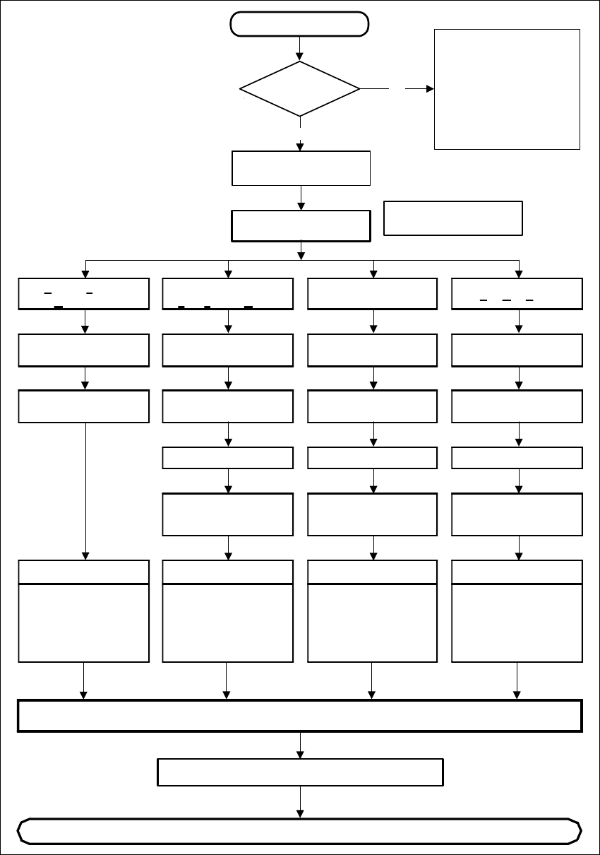
Fig. 6.7 - 3 Flow chart ’Programming and testing a package form (GF), part - line computer
Irregular
FDC
Regular
F
ully defined Comp.
P
artially defined
C
omponent
Ball Grid Array
Body dimensions
Body dimensions Body dimensions
SAVE
Continue programming at the station
New component
GF file
present?
No
Yes
Program additional file information
Please note that when
standard package form
are used by TEST
COMPONENT,
the component detection
may be changed (copy the
GF file [ _.SST file ] again,
if necessary).
Program GF file with
No. > 1499
Select package type
Program GF file with
No. > 1499
Enter
user comment
Enter
user comment
Enter
user comment
Enter
user comment
GF nominal dimensions
and tolerances
GF nominal dimensions
and tolerances
GF nominal dimensions
and tolerances
GF nominal dimensions
and tolerances
Program
group of leads,
lead model data
Program
group of leads,
lead model data
Program
ball pitch,
lead model data
Editing data
Nozzle type (camera)
sensor system type,
vacuum checks/
editing parameters/
reduction in acceleration
Editing data
Nozzle type (camera)
sensor system type,
vacuum checks/
editing parameters/
reduction in acceleration
Editing data
Nozzle type (camera)
sensor system type,
vacuum checks/
editing parameters/
reduction in acceleration
Editing data
Nozzle type (camera)
sensor system type,
vacuum checks/
editing parameters/
reduction in acceleration
6 Vision functions User Manual SIPLACE F5/F5 HM
6.7 Guidelines for Describing Package Forms Software version SR.407.xx 01/2001 US Edition
356
6
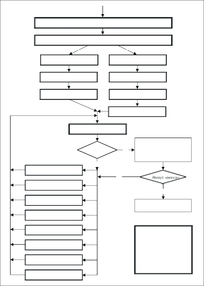
Fig. 6.7 - 4 Flow chart: ’Programming and testing a package form (GF)’, part 2 - station computer
Display component
Always identical?
No
No
Yes
Error message
occurred?
Yes
Check GF (component), press
Return for next meas. step
Check GF (component), press
Return for next meas. step
Important note:
The manipulation of
components at the station
must remain the exception,
rather than the rule.
In general, only a few
components have to be
changed.
1. Handling error: pick-up angle,
nozzle type, CO on nozzle etc.
2. Display component
3. Modify lighting
4. Modify measuring modes
and measuring parameters
5. Modify component dimension
6. Modify pin/ball contrast
7. Modify pin/ball dimensions
8. Program contrast
(program table)
Modify package form as required in "Vision system“ and "Test component“
Send program and set-up with this package form to the station and set up
Revolver head
Pick-up GF (component)
Pick&Place placement head
Pick up GF (component)
Measure component
Display component
Measure GF (component)
Repeat meas. process several
Repeat placement process
several times !
times (move component onto
nozzle to simulate picking up
different components)
and check results

User Manual SIPLACE F5/F5 HM 6 Vision functions
Software version SR.407.xx 01/2001 US Edition 6.7 Guidelines for Describing Package Forms
357
6.7.3 Shapes and possible measuring methods for rough (G) and fine centering (F)
If one or more of the results are outside the tolerance, the component will not be placed. 6
If the component cannot be centered correctly, additional measuring methods may be omitted.
You should, however, carry out all the rough centering steps since these reduce the size of the
measuring window. 6
Design
SIZE
ROW
CORNER
Lead : combined
analysis windows
Lead: separate
analysis windows
GRID
BALL
Result of the
last measuring step
PDC without lead G/F
∆X, ∆Y, (∆φ), Component
length, width, (quality)
PDC rounded image G/F F Angular tolerance
Small FDCs, e.g.
2 leads
G/F F
∆X, ∆Y, (∆φ), Component
length, width, (quality)
FDC, regular with short
rows of PINs
GF
four-
sided
F
Not
four-
sided
F
Max. deviation from the
spacing: ∆X, ∆Y, ∆φ,
(quality)
FDC, regular with long
rows of PINs
GF
four-
sided
F
Not
four-
sided
F
Max. deviation from the
spacing: ∆X, ∆Y, (∆φ),
quality
FDC irregular with
short rows of PINs
G(G)F F
∆X, ∆Y, number of PINs
(quality), max. deviation
from the spacing
FDC, irregular with
long rows of PINs
G(G)F F
∆X, ∆Y, number of PINs
(quality), max. deviation
from the spacing
FDC, irregular with one
row of PINs, several
PIN models or spac-
ings
GG F
∆X, ∆Y, (∆φ), standardized
lead deviation (quality)
Number of PINs, second-
ary offset
FDCs with circular seg-
ment PIN arrange-
ments
(G) G F
∆X, ∆Y, (∆φ), standardized
lead deviation (quality)
Number of PINs, second-
ary offset
BGA, flip-chip G G F
∆X, ∆Y, (∆φ), spacing,
angle, quality)