00192662-01.pdf - 第221页
User Manual SIPLAC E F5/F5 HM 6 Vision functions Software version SR.407.xx 01/2001 US Edition 6.1 The vision systems on the placement machine 221 6 V ision functions 6.1 The vision systems on the placement machine The q…
5 Single Functions User Manual SIPLACE F5/F5 HM
5.3 Single functions, Transport Software version SR.407.xx 01/2001 US Edition
220
User Manual SIPLACE F5/F5 HM 6 Vision functions
Software version SR.407.xx 01/2001 US Edition 6.1 The vision systems on the placement machine
221
6 Vision functions
6.1 The vision systems on the placement machine
The quality requirements concerning the accuracy of automatic placement systems are constantly
rising, for several reasons: 6
– continuing miniaturization of components,
– increasing lead connection density,
– increasing complexity of PCBs and
– increasing component density.
6
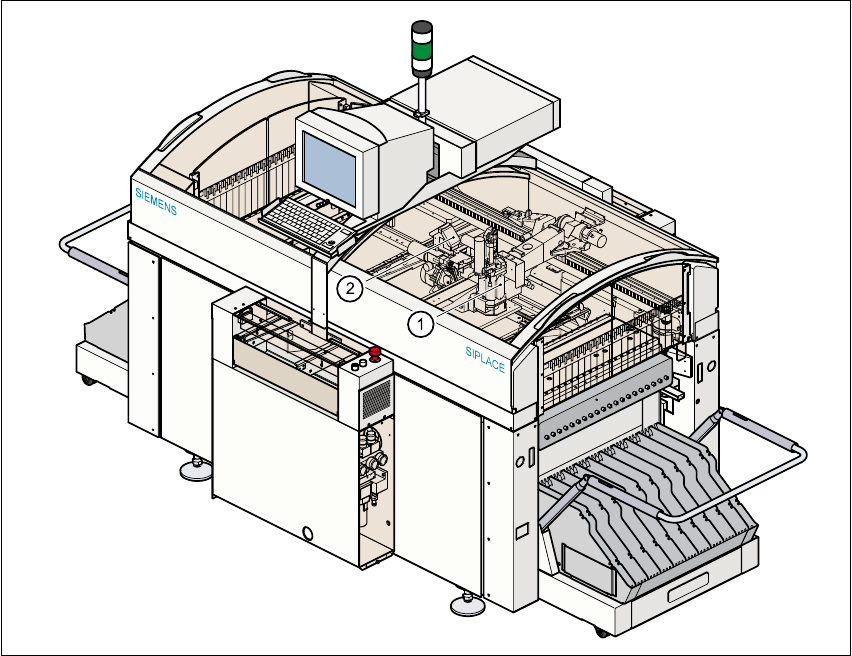
Fig. 6.1 - 1 Position of the placement heads on the machine
(1) Pick&Place head
(2) 6-segment Collect&Place head (F
5
)
6-segment or 12-segment Collect&Place head / DLM1 (F
5
HM)

6 Vision functions User Manual SIPLACE F5/F5 HM
6.1 The vision systems on the placement machine Software version SR.407.xx 01/2001 US Edition
222
To help meet these requirements, high-precision mechanical components are combined with op-
tical centering and recognition systems (known as vision modules) for components and PCBs. 6
The placement machine has a gantry (see Fig. 6.1 - 1
). The gantry supports: 6
– a 12-segment Collect&Place head (see Fig. 6.1 - 2
) and a Pick&Place head (F
5
machine) or
– a 6-segment or 12-segment Collect&Place head / DLM1 and a Pick&Place head (F
5
HM ma-
chine).
A PCB camera system is mounted on the underside of the head mount (see Fig.
6.1 - 6
). The vision analysis unit plugs into the control unit (see item 1 in Fig. 6.1 - 7). The compo-
nent and PCB cameras and the vision analysis unit together form the vision system. 6
6.1.1 Component vision module on the 12-segment Collect&Place head
The component vision module (see item 2 in Fig. 6.1 - 2) essentially consists of the following mod-
ules: 6
– Optical lens
– CCD chip for creating an electronic image of the component
– CCD camera amplifier
– Three illumination levels – flat, average and steep – for optimum illumination of a wide
range of component shapes
–“Illumination control” board for setting the intensity of the individual illumination levels.