00192662-01.pdf - 第65页
User Manual SIPLACE F5/F 5 HM 1 Introduction and technical data Software version SR.407.xx 01/2001 US Edition 1.14 Overview of t he modules - vision systems 65 1.14.2 T echnical dat a - st andard CO vision module on the …

1 Introduction and technical data User Manual SIPLACE F5/F5 HM
1.14 Overview of the modules - vision systems Software version SR.407.xx 01/2001 US Edition
64
1.14 Overview of the modules - vision systems
Every machine has 1
– a PCB vision module on the Collect&Place head,
– a fine-pitch component vision module on the machine base, and
– a PCB vision module on the underside of the X-axis gantry
1
The vision evaluation unit is located on the machine’s control unit. The component vision module
is used to 1
– determine the precise position of the component at the nozzle, and
– the geometry of the package form.
1
The PCB vision module uses fiducials on the PCB to determine 1
– the position of the PCB,
– its rotational angle,
– and the PCB distortion.
Damaged PCBs or subpanels are marked with ink spots. The PCB vision module scans the ink
spots, and signals that these circuits should not be placed. 1
The PCB vision module also uses fiducials on the feeders to determine the precise component
pick-up position. This is particularly important for tiny components. 1
1.14.1 Technical data of the component vision module on the 12-segment C&P head
Max. component dimensions 0.5mm x 1.0mm to 18.7mm x 18.7mm
Component range
0402 to PLCC44
including BGA, µBGA, flip-chip, TSOP, QFP
PLCC, SO to SO32, DRAM
Minimum lead pitch ≥ 0.5 mm
Field of view 24mm x 24mm
Method of illumination Front lighting (3 levels programmable as required)

User Manual SIPLACE F5/F5 HM 1 Introduction and technical data
Software version SR.407.xx 01/2001 US Edition 1.14 Overview of the modules - vision systems
65
1.14.2 Technical data - standard CO vision module on the 6-segment C&P head
1.14.3 Technical data of the DCA vision module on the 6-segment C&P head
1.14.4 Technical data - fine-pitch vision module
1.14.5 Technical data – PCB vision module
Component dimensions 0.5mm x 1.0mm to 32mm x 32mm
Component range
0603 to 32mm x 32mm
PLCC, SO, QFP, TSDP, SOT, MELF, CHIP, IC BGA
Minimum lead pitch 0.5 mm
Field of view 24mm x 24mm
Method of illumination Front lighting (3 levels programmable as required)
Component dimensions 0.25mm x 0.5mm to 13mm x 13mm
Component range Components up to 13mm x 13mm, flip-chips, bare dies
Minimum lead pitch 0.2 mm
Minimum ball diameter 110 µm
Field of view 15.7mm x 15.7mm
Method of illumination Front lighting (4 levels programmable as required)
Max. component size
32mm x 32mm (single measurement)
55mm x 55mm (multiple measurement)
(larger components available upon request)
Component range
PLCC, LCCC, QFP, SO, BGA, flip-chip,
components with leads up to 55mm x 55mm
(J-leads and gull wings, balls, bumps)
Minimum lead pitch 0.2 mm
Field of view 38mm x 38mm
Method of illumination Front lighting (3 levels programmable as required)
Fiducials Up to 3 per placement program
Local fiducials Up to 2 per PCB (may be of different types)
Library size Up to 255 types of fiducial – system fiducials ≥ 249
Image processing Gray scale value-based correlation principle
Method of illumination Front lighting
Fiducial recognition time per fiducial/ink spot 0.4 s
Field of view 5.7 mm x 5.7 mm
1 Introduction and technical data User Manual SIPLACE F5/F5 HM
1.15 Overview of the modules - PCB conveyor Software version SR.407.xx 01/2001 US Edition
66
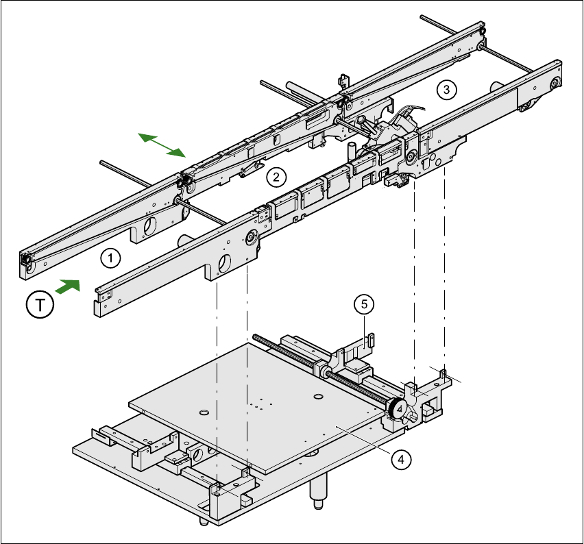
1.15 Overview of the modules - PCB conveyor
1.15.1 Structure of the PCB conveyor
The machine is supplied with a single conveyor as standard. The dual conveyor is available as an
option. The left or the right side of the PCB conveyor can be used as the stationary side, as re-
quired. 1
1
Fig. 1.15 - 1 PCB conveyor - single conveyor
(1) Input conveyor (2) Center conveyor
(3) Output conveyor (4) Lifting table
(5) Width adjustment T PCB transport direction 1