00192662-01.pdf - 第380页
6 Vision functions User Manua l SIPLACE F5/F5 HM 6.7 Guidelines for Describing Pa ckage Forms Software version S R.407.xx 01/2001 US Edition 380 A contrast of a t least 4 color sc ales betwe en the le ad and body i s req…
User Manual SIPLACE F5/F5 HM 6 Vision functions
Software version SR.407.xx 01/2001 US Edition 6.7 Guidelines for Describing Package Forms
379
edges. It is, however, less suitable for displaying bright component bodies and ceramic compo-
nents. 6
Middle illumination level 6
The middle illumination level can be used universally with a wide range of components. With bright
component bodies, ceramic components, µBGAs and flip-chips it should, however, only be used
at lower intensity levels. 6
Steep illumination level 6
The main application for the steep illumination level is for reflective leads, ceramic components
and bright component bodies. It is less suitable for bare dies, flip-chips or µBGAs. 6
NOTE 6
Most components will require a combination of these illumination levels to achieve optimum illu-
mination. Using one illumination level will only be successful in exceptional cases.
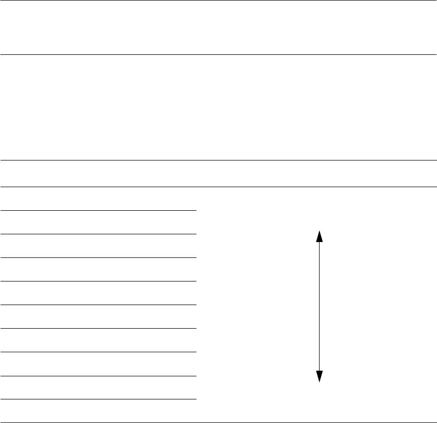
6.7.9.2 Pseudo color representation
The pseudo color representation provides a powerful and objective assessment of the illumina-
tion, by representing a brightness value in a color. 6
Color scale Brightness
white light
yellow
orange
red
brown
green
light blue
blue
violet
black dark

6 Vision functions User Manual SIPLACE F5/F5 HM
6.7 Guidelines for Describing Package Forms Software version SR.407.xx 01/2001 US Edition
380
A contrast of at least 4 color scales between the lead and body is required for a measurement. In
the ‘Illumination’ menu of the package form manipulator, components are displayed in the pseudo
color representation on the station computer monitor. 6
6.7.9.3 Settings for Illuminating Standard Components
The standard range of components includes chips (0402 to 2220), tantalum capacitors, Melf com-
ponents, PLCCs, QFPs, SOs, SOJs, TSOPs, ICs, power components, flip-chips, µBGAs, BGAs
and bare dies. 6
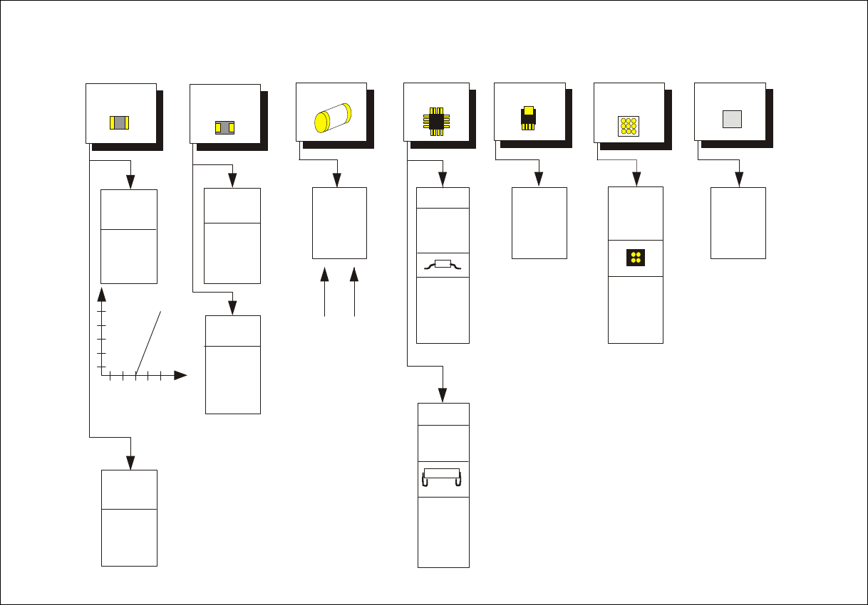
For the components which are listed below the GF interpreter in the station computer uses the
default illumination parameters listed in Fig. 6.7 - 12
: 6
– Chips (0402 to 2220)
– Tantalum capacitors (component bodies, non-reflective)
– Melf
– PLCC, QFP, SO, SOJ, TSOP, ICs, power ICs
– Flip-chips, µBGAs, BGAs
– Bare dies
As a rule you will not need to change the illumination parameters for the standard components.6
User Manual SIPLACE F5/F5 HM 6 Vision functions
Software version SR.407.xx 01/2001 US Edition 6.7 Guidelines for Describing Package Forms
381
Fig. 6.7 - 12 Illumination parameters for components on the 6-segment
Collect&Place head camera (DCA-option)
BGA, µBGA
Flip Chip
BGA,
µBGA,
Flip Chip
Power IC
IC
Gullwing
SO, SOT,
TSOP
QFP,
J-Lead
PLCC
Melf
Illumination
level
Brightness
Tantalum
capacitor
General
Reflective
body
150
255
Contrast
sensitivity
Chip
0805 and
larger
0402,
0603
Bare Die
0201,
50
50
50
50
0
50
80
100
230
230
20
20
X plane:
flat:
middle:
steep:
X plane:
flat:
middle:
steep:
X plane:
flat:
middle:
steep:
X plane:
flat:
middle:
steep:
X plane:
flat:
middle:
steep:
X plane:
flat:
middle:
steep:
X plane:
flat:
middle:
steep:
50
50
50
50
200
100
40
40
0
80
50
50
0
0
100
20
0
80
50
50
150
30
0
0
0
0
50
110
X plane:
flat:
middle:
steep:
X plane:
flat:
middle:
steep:
X plane:
flat:
middle:
steep:
Adjusting the illumination of standard components