00192662-01.pdf - 第182页
5 Single Functions User Manual SIPLACE F5/F5 HM 5.2 Single functions, Gantry Software version SR.407.x x 01/2001 US E dition 182 5.2.1.1 Functions In the "Rev olve r head func tions" sc reen, the fu nction s de…
User Manual SIPLACE F5/F5 HM 5 Single Functions
Software version SR.407.xx 01/2001 US Edition 5.2 Single functions, Gantry
181
(5) Nozzle offset, Collect&Place head
(6) Nozzle configuration, Collect&Place head
(7) Nozzle changer configuration, Collect&Place head
(8) Nozzle changer configuration Pick&Place head
(9) Fluxer head functions
5
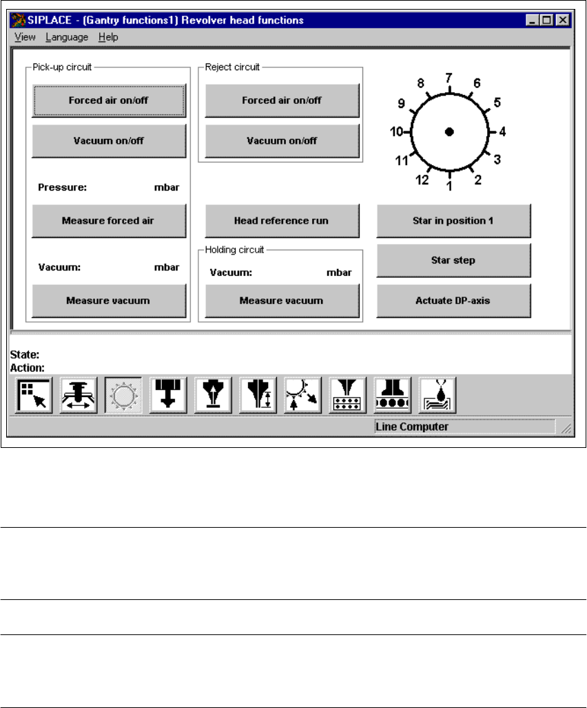
Fig. 5.2 - 2 "Revolver head functions" screen (12-nozzle Collect&Place head)
5
NOTE
Since the functions in the "Revolver head functions" screen are identical for the 6-nozzle and 12-
nozzle Collect&Place heads, they will not be described separately. 5
NOTE
The current position of the Collect&Place head segment is shown by the graphic above the "Star in
position 1" button. 5

5 Single Functions User Manual SIPLACE F5/F5 HM
5.2 Single functions, Gantry Software version SR.407.xx 01/2001 US Edition
182
5.2.1.1 Functions
In the "Revolver head functions" screen, the functions described below are available to help you
test the Collect&Place head. 5
– Vacuum test in the pick-up position
– Vacuum test in the reject position
– Vacuum test in the holding circuit
– Revolver head functions
The functions are triggered by clicking the appropriate button. 5
Pick-up circuit - Forced air on/off 5
When this function is activated, the forced air to the nozzle in the pick-up position is either
switched on or off.
Å In the "Pick-up circuit" area, click the Forced air on/off button.
This switches the forced air on or off.
Pick-up circuit - Vacuum on/off 5
When this function is activated, the vacuum at the nozzle in the pick-up position is either
switched on or off.
Å In the "Pick-up circuit" area, click the Vacuum on/off button.
This switches the vacuum on or off.
Pick-up circuit - Measure forced air 5
When this function is activated, forced air at the pick-up position is measured.
Å Switch on the forced air (using the "Forced air on/off" function in the "Pick-up circuit" area).
Å Click the Measure forced air button in the "Pick-up circuit" area.
The forced air is measured and the result displayed in [mbar] above the button.
NOTE
The value displayed after the measurement is taken does not correspond to the actual values at
the nozzle.
When calibrating the machine, you must use a manometer to establish the values (see Adjustment
instructions or the Service Manual). 5
Pick-up circuit - Measure vacuum 5
When this function is activated, vacuum at the pick-up position is measured.
Å Switch on the vacuum (using the "Vacuum on/off" function in the "Pick-up circuit" area).
Å Click the Measure Vacuum button in the "Pick-up circuit" area.
The vacuum is measured and the result displayed in [mbar] above the button.
User Manual SIPLACE F5/F5 HM 5 Single Functions
Software version SR.407.xx 01/2001 US Edition 5.2 Single functions, Gantry
183
Reject circuit - Forced air on/off 5
When this function is activated, the forced air at the nozzle in the reject position is switched on or
off.
Å Click the Forced air on/off button in the "Reject circuit" area.
The forced air is switched on or off.
Reject circuit - Vacuum on/off 5
When this function is activated, the vacuum to the nozzle in the reject position is switched on or
off.
Å Click the Vacuum on/off button in the "Reject circuit" area.
The vacuum is switched on or off.
Head reference run 5
This function is used to start a head reference run of all the head axes, or in other words, all head
axes travel to their origin. The gantry axes travel over the reject container and discard compo-
nents in a defined manner.
Å Click the Head reference run button.
The head axes execute a head reference run.
Holding circuit - Measure vacuum 5
When this function is activated, the vacuum at the nozzle in the holding circuit is measured.
Å Click the Measure vacuum button in the "Holding circuit" area.
The vacuum is measured and the result displayed in [mbar] above the button.
Star in position 1 5
This function is used to bring the Collect&Place head into a defined starting position.
Å Click the Star in position 1 button.
The Collect&Place head is moved round so that segment 1 is in the pick up and placement
position (lowest position). In addition the Collect&Place head and the z-axis perform a refer-
ence run.
RV head indexing 5
This function is used to move the Collect&Place head. Each time you click the button the Col-
lect&Place head is moved round by one segment.
Å Click the RV head indexing button.
The Collect&Place head is moved by one segment.
The current positions of the segments is displayed in the graphic.