00192662-01.pdf - 第193页
User Manual SIPLAC E F5/F5 HM 5 Single Functions Software version SR.407.xx 01/2001 US Edition 5.2 Single functions, Gantry 193 5 Fig. 5.2 - 8 "Nozzle offset" screen (12-noz zle Collect&Place head) NOTE Sin…
5 Single Functions User Manual SIPLACE F5/F5 HM
5.2 Single functions, Gantry Software version SR.407.xx 01/2001 US Edition
192
5.2.5 "Nozzle offset" screen
5
Å In the current screen for the single functions for Gantry, click the symbol .
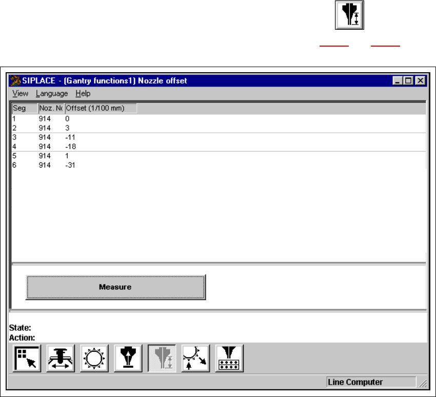
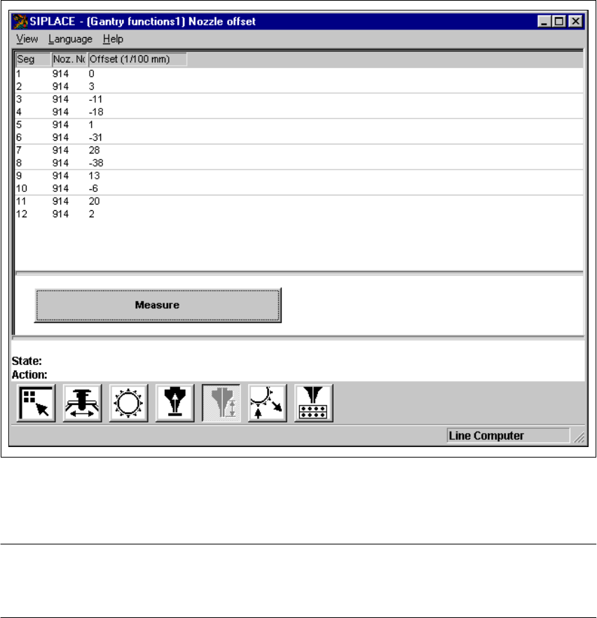
The user interface is switched to the "Nozzle offset" screen (see Fig. 5.2 - 7
and 5.2 - 8).
5
Fig. 5.2 - 7 "Nozzle offset" screen (6-nozzle Collect&Place head)
User Manual SIPLACE F5/F5 HM 5 Single Functions
Software version SR.407.xx 01/2001 US Edition 5.2 Single functions, Gantry
193
5
Fig. 5.2 - 8 "Nozzle offset" screen (12-nozzle Collect&Place head)
NOTE
Since the functions in the "Nozzle offset" screen are identical for the 6-nozzle and 12-nozzle Col-
lect&Place heads, they will not be described separately. 5
5 Single Functions User Manual SIPLACE F5/F5 HM
5.2 Single functions, Gantry Software version SR.407.xx 01/2001 US Edition
194
5.2.5.1 Functions
In the "Nozzle offset" screen only the "Measure" button is available. This is used to start a evalu-
ation of the nozzle height for all nozzles.
Measure 5
When this function is activated, after a vacuum check the gantry moves the placement head to a
defined position above the board conveyor. The z-axis is lowered until the nozzle touches the con-
veyor, the procedure is then repeated for each nozzle. In this way, you can measure the height of
each nozzle.
The gantry then returns to its starting position. 5
Å Click the Measure button.
This starts the procedure used to measure nozzle height.
The values determined are displayed in the column "Offset (1/100 mm)" for each of the noz-
zles. These values can, for example, be used to determine whether the nozzle on a particular
segment broken.