00192662-01.pdf - 第457页
User Manual SIPLAC E F5/F5 HM 10 Component han dling Software version SR.407.xx 01/2001 US Edition 10.5 Used tape cutter 457 10.5.2 Inserting the t ape into the t ape cutter 10 Fig. 10.5 - 2 Inserting the tape into the t…
10 Component handling User Manual SIPLACE F5/F5 HM
10.5 Used tape cutter Software version SR.407.xx 01/2001 US Edition
456
10.5 Used tape cutter
10.5.1 General
The placement system has a used tape cutter at each of the two component table locations. It is
used to cut off the waste tape. The cut pieces of tape drop into the waste tape container in the
component table. 10
Å Empty the waste tape container every day.
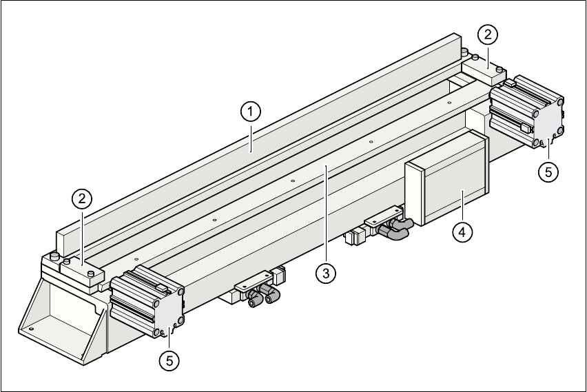
Fig. 10.5 - 1 Used tape cutter
(1) Stationary cutting blade
(2) Retainer
(3) Moving cutting blade
(4) Electronic control unit
(5) Short stroke cylinder
User Manual SIPLACE F5/F5 HM 10 Component handling
Software version SR.407.xx 01/2001 US Edition 10.5 Used tape cutter
457
10.5.2 Inserting the tape into the tape cutter
10
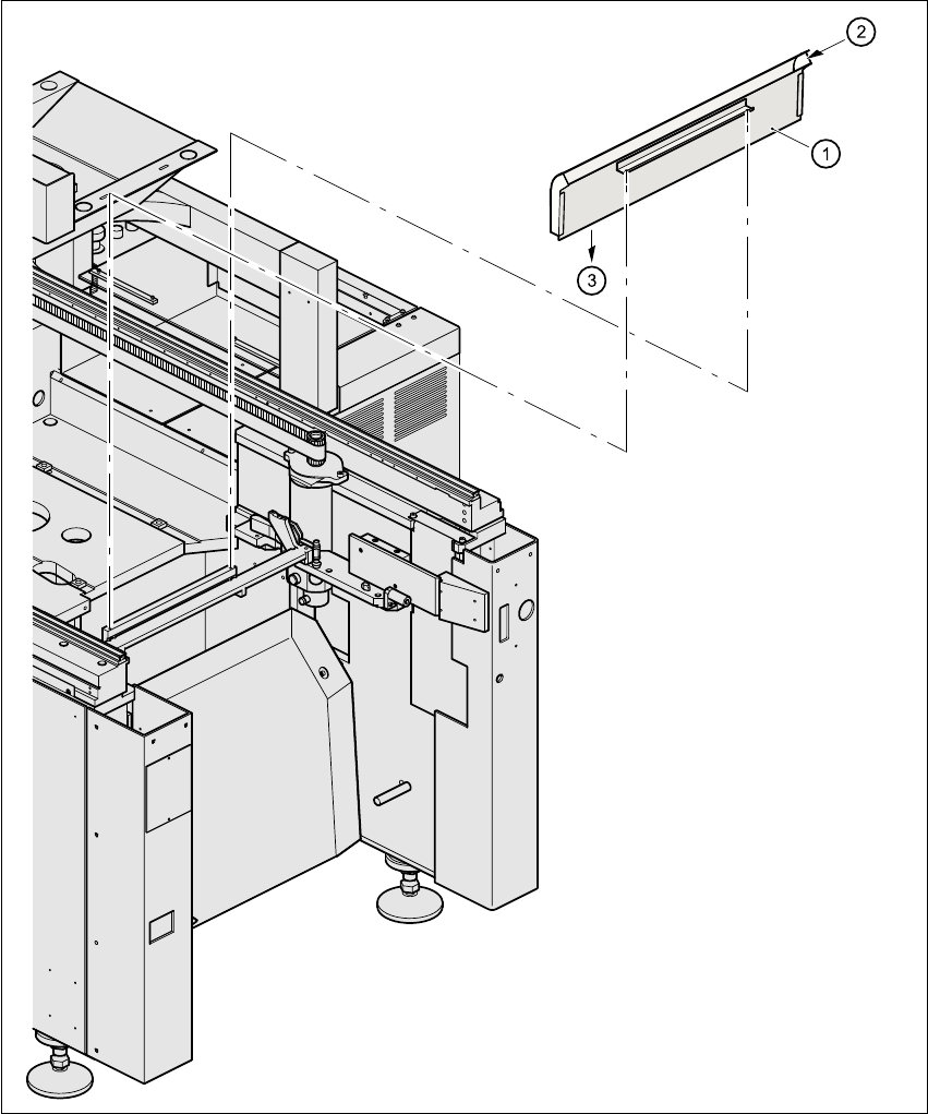
Fig. 10.5 - 2 Inserting the tape into the tape cutter
(1) Used tape channel (2) Used tape
(3) To used tape cutter 10
10 Component handling User Manual SIPLACE F5/F5 HM
10.5 Used tape cutter Software version SR.407.xx 01/2001 US Edition
458
PLEASE NOTE
On SIPLACE automatic placement systems, only use the tape feeder modules specified for these
machines. The used tape channel which removes the used tape is located upstream of the feeder
modules. 10
Å Insert the tape into the feeder as described in the corresponding section.
Å Guide the used tape into the used tape channel of the cutter as described in Fig. 10.5 - 2
The used tape guide channels are located upstream of the feeder modules
(see pos. 1 in fig. 10.5 - 2
). They are positioned directly above the used tape cutters (see pos. 3
in fig. 10.5 - 2
). 10
The tape is automatically guided through the used tape guide channel into the used tape cutter
below. There, the tape is shredded by the pneumatically-actuated cutting blade. The waste tape
then passes via the waste tape chute into the waste container. 10
10
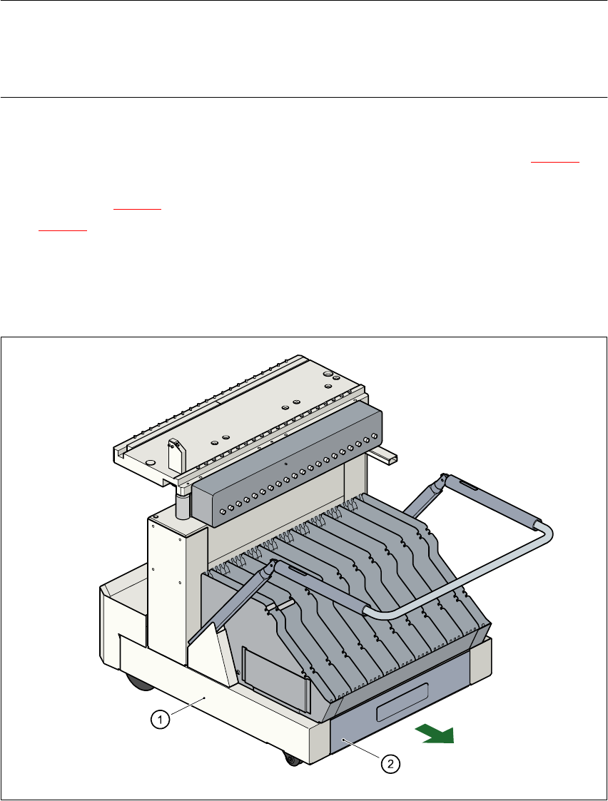
Fig. 10.5 - 3 Used tape container in the component changeover table, withdrawable
(1) Component changeover table
(2) Used tape container, withdrawable