00192662-01.pdf - 第247页
User Manual SIPLAC E F5/F5 HM 6 Vision functions Software version SR.407.xx 01/2001 US Edition 6.3 Component vision systems 247 6 Fig. 6.3 - 1 Regular component Key to Fig. 6.3 - 1 (1) Axi s of sym metry 6 Criteria for i…
6 Vision functions User Manual SIPLACE F5/F5 HM
6.3 Component vision systems Software version SR.407.xx 01/2001 US Edition
246
provide information on deviations in position, the rotational angle, lead condition, and the mapping
quality of the component. 6
New illumination methods and special algorithms for obtaining the component parameters have
been developed for BGAs and flip-chips. This means that this new generation of components
can now be optically centered.
The IC head returns any components that cannot be optically centered to the waffle pack tray for
further analysis.
6
6
6
6
6.3.4 Criteria for Recognition of Components
Shape of the Components 6
Optical component centering allows both regular and irregular components to be centered. The
maximum number of leads, horizontally and vertically, is 99 in each case. 6
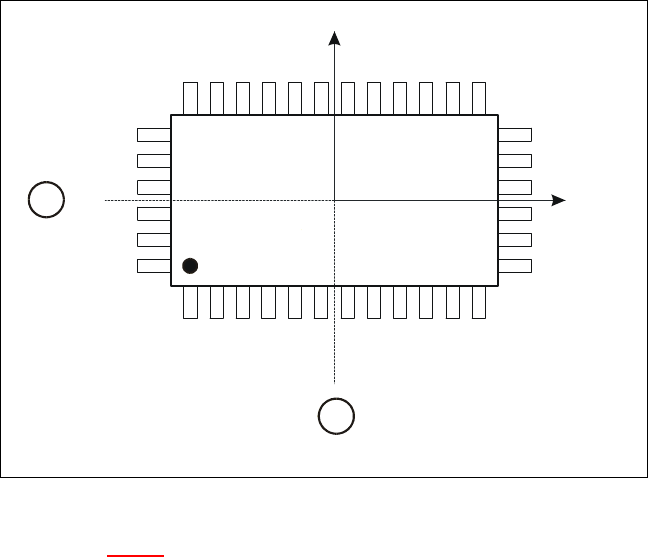
Criteria for regular components 6
Definition:
A component is deemed to be regular when it satisfies the following four conditions: 6
– rectangular package shapes (special case: square shape)
– only one lead type per side
– only one lead group per side
– opposite lead groups located symmetrically with respect to the two main axes
(X and Y axes).
User Manual SIPLACE F5/F5 HM 6 Vision functions
Software version SR.407.xx 01/2001 US Edition 6.3 Component vision systems
247
6
Fig. 6.3 - 1 Regular component
Key to Fig. 6.3 - 1
(1) Axis of symmetry
6
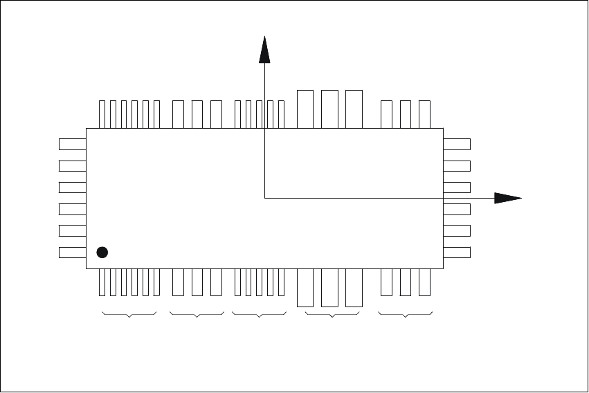
Criteria for irregular components 6
Definition:
A component is deemed to be irregular when it does not satisfy the conditions for regular compo-
nents. 6
Additional conditions for centering with the component vision module: 6
– In any one row up to 3 different lead types are permitted.
– In any one row up to 15 groups are permitted.
6
Y
X
Pin 1
1
1
6 Vision functions User Manual SIPLACE F5/F5 HM
6.3 Component vision systems Software version SR.407.xx 01/2001 US Edition
248
6
Fig. 6.3 - 2 Example of irregular components
Pitch deviation 6
The pitch deviation (which is the distance from the center of one lead to the center of the next) can
be edited separately for each component in the GF editor. If this value is exceeded during the vi-
sion inspection, the component will not be centered and therefore not placed. 6
Limit values for quality measurement 6
Components exceeding the limit values for quality measurement will be rejected and, therefore,
not placed: 6
– Difference in the number of leads between the original and the model.
– Pitch deviation larger than the value in the GF file.
– Larger orthogonality error than specified in the GF file.
– Larger deviations of the external dimensions.
– Deviation of the central point greater than the permitted positional tolerance for pick-up.
X
Pin 1
Y
X
Pin 1
Type 1
Group 1
Type 2
Group 1
Type 1
Group 2
Type 3
Group 1
Type 2
Group 2