DFD6361-Maintenance.pdf - 第148页
B-76 Procedur es for mo unting the fl ange (2. 2 kW spi ndle) (C ontinued) St e p N o . Do This 8 Press the <C lose> button to release l ock of the t ouch panel. 9 Press the <EXIT> but ton to call up t he MAI…
B-75
Procedures for mounting the flange (2.2 kW spindle)
Step No. Do This
(Continued from the previous section)
1
Clean the flange A and spindle taper section with lint-free waste
moistened with alcohol, and then blow air to remove water.
2
Fit the flange A onto the spindle taper section.
3
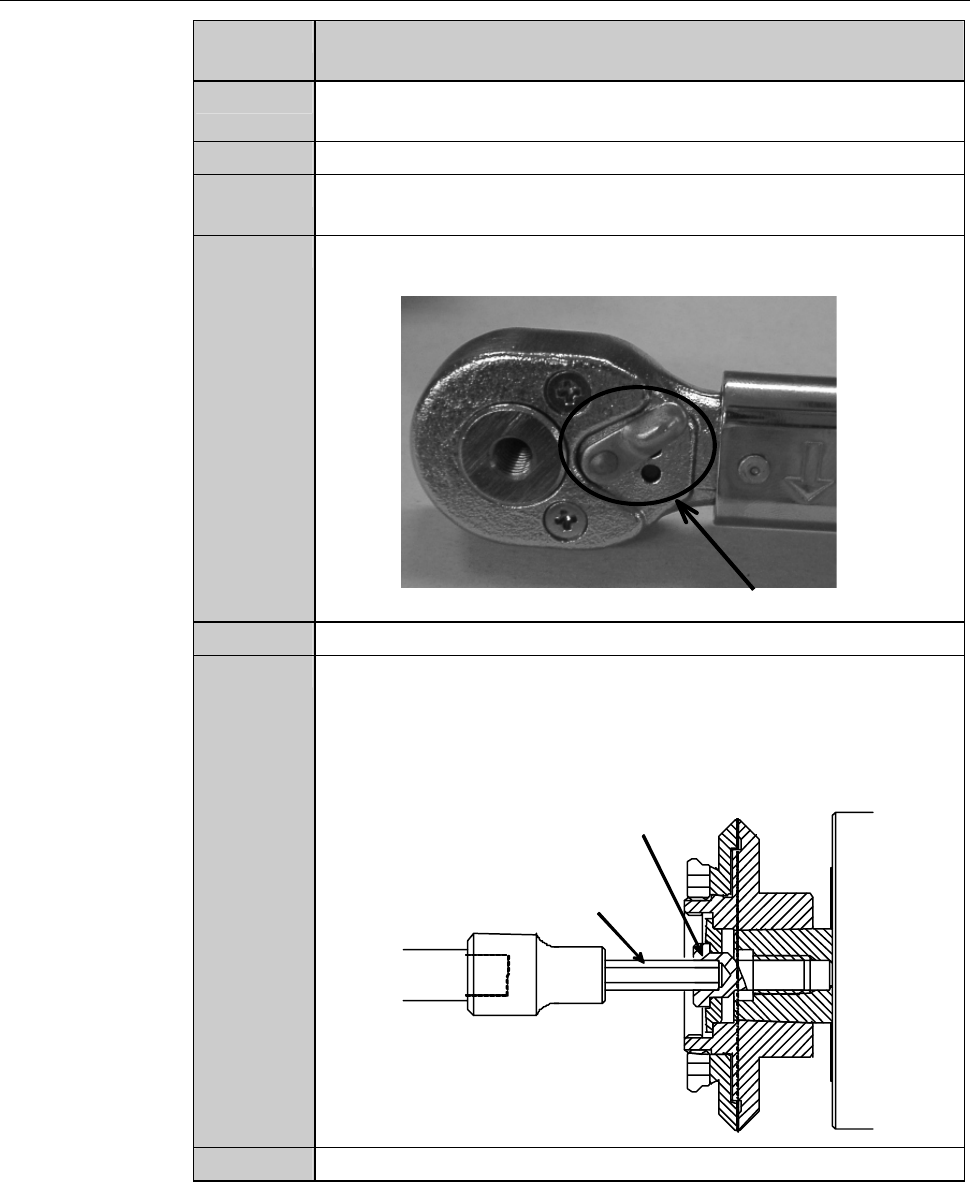
Adjust the torque of the torque wrench.
Torque for 2.2kW spindle: 8.0 N·m
4
Adjust the direction selector lever so that specified torque will be
produced when you turn the torque wrench clockwise.
Direction selector lever
5
Have on hand the torque wrench set.
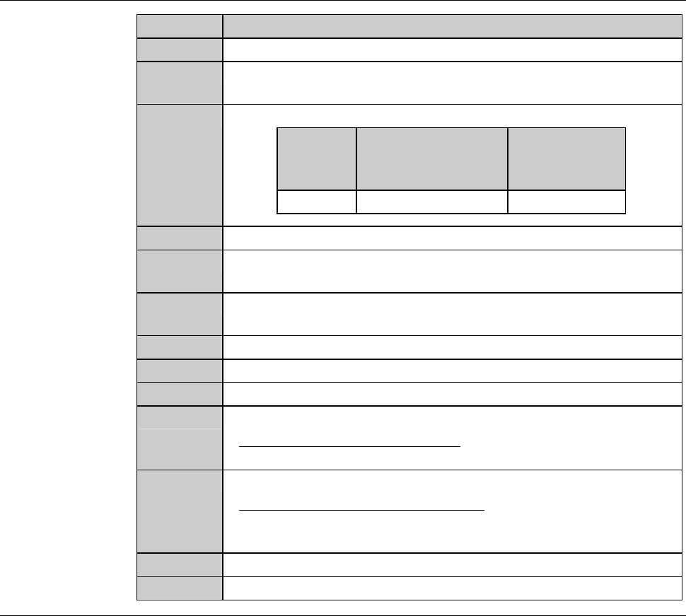
6
Using the torque wrench set, torque the lock bolt to 8.0 N·m.
- To tighten the bolt, turn the torque wrench clockwise.
- Turn the torque wrench slowly.
- When the torque reaches the specified one, you feel light
resistance.
Lock bolt
Bit
7
Close the splash cover.
B-76
Procedures for mounting the flange (2.2 kW spindle) (Continued)
Step No. Do This
8
Press the <Close> button to release lock of the touch panel.
9
Press the <EXIT> button to call up the MAIN MENU
[screen 0.0].
10
Turn ON the spindle.
Blade
diameter
[inch]
Maximum spindle
rotating speed
[min
-1
(rpm)]
Time to reach
maximum
speed [s]
3 30,000 30
11
Turn OFF the spindle.
12
Call up the BLADE REPLACEMENT screen [screen 4.1].
- The Y-axis moves to its origin position.
13
Press the Disco's logo button located at the upper left of the
screen to lock up the touch panel.
14
Open the splash cover.
15
Torque the lock bolt to 8.0 N·m again.
16
Press the <Close> button to release lock of the touch panel.
17
Perform a conditioning operation.
- For the conditioning procedures;
See the section C-2, [Hub Mount/Flange Conditioning].
18
Install the blade.
- For the blade installation procedure;
See the section B-6, [Blade Maintenance] of the Operation
Manual.
19
Close the splash cover.
20
Press the <System Initial> button to effect system initialization.
B-77
2-6. Hub Mount Replacement (2.2 kW Spindle)
[Optional Accessory]
Operation flow
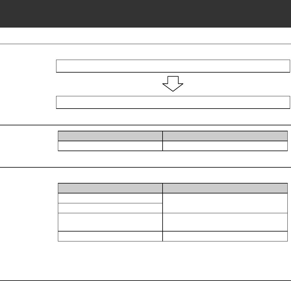
The hub mount replacement procedure consists of the following steps.
2-6-1 Removing the hub mount (2.2 kW spindle)
2-6-2 Mounting the hub mount (2.2 kW spindle)
Type of the spindle and hub mount
Spindle Name
2.2 kW spindle Hub mount
Before operation
Have on hand the following jigs for hub mount replacement.
Jig Name Function
Bit
Torque wrench
Used to remove or mount the lock bolt.
Nut demounting jig Used to remove or mount the lock nut for
hub.
Hub mount removing jig set Used to remove the hub mount.
[Other]
Alcohol / Lint-free waste