DFD6361-Maintenance.pdf - 第220页
C-8 2-1-2. Hu b mount cond itioning Hub mount mov ement of condi tioning When the hub ty pe blade is used, the axis moves as illustrate d below in the hub mount conditioning. The first spark-out operat ion performed afte…
C-7
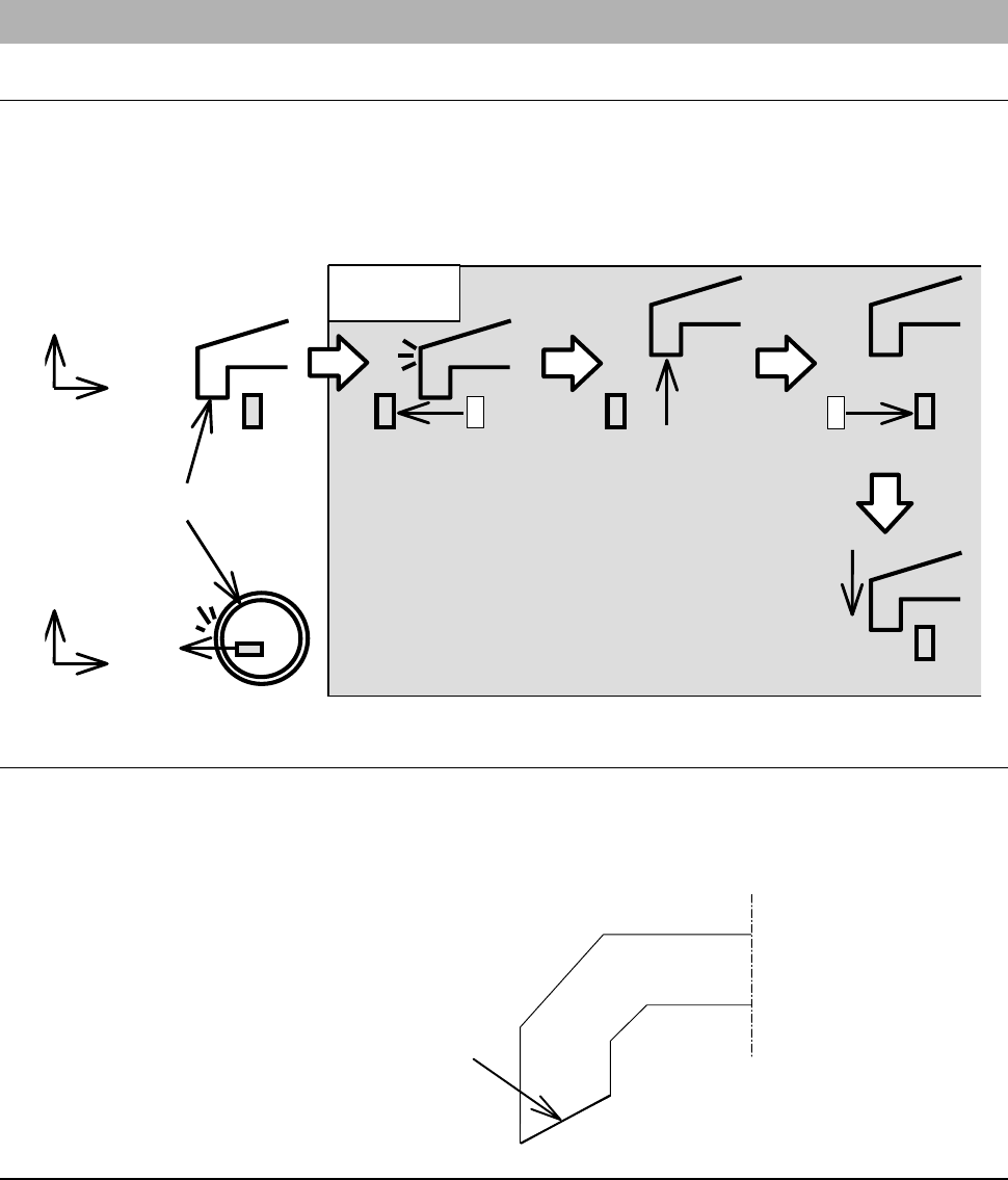
2-1-1. Flange conditioning
Movement in flange A conditioning
When the flange type blade is used, the axis moves as illustrated below in the
flange A conditioning.
The first spark-out operation performed after Y-axis indexing always starts
from the inside of the flange.
Flange
A
End face
Y
X
Z
X
A
Spark-out
A
Flange escape
A
Tip return
A
Flange return
1cycle
Shape of the flange after conditioning
Conditioning is conducted so that the flange A end face will be highest at the
outer end and enclose the blade.
The shape of the flange after conditioning should be as illustrated below.
End face
Flange (A)
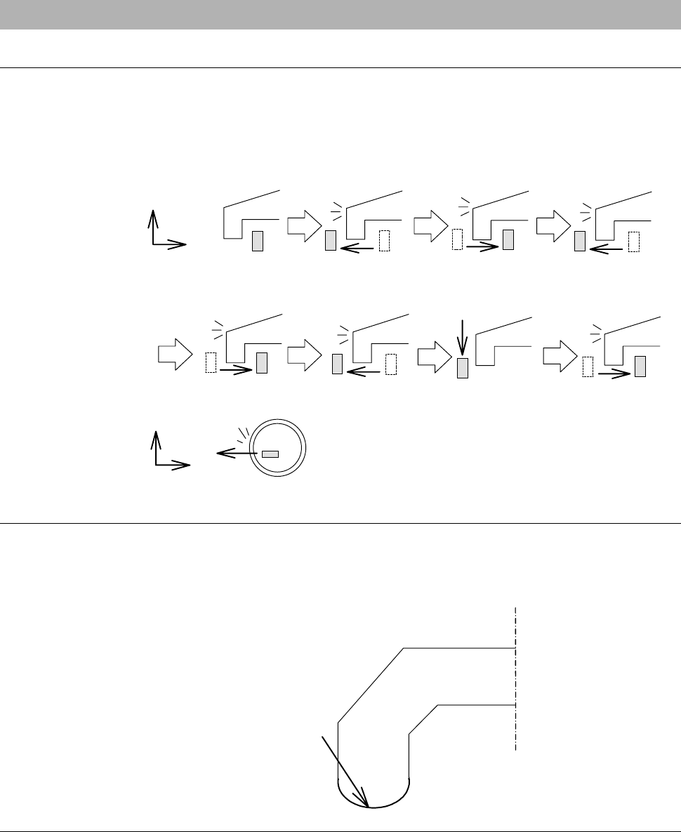
C-8
2-1-2. Hub mount conditioning
Hub mount movement of conditioning
When the hub type blade is used, the axis moves as illustrated below in the
hub mount conditioning.
The first spark-out operation performed after Y-axis indexing starts alternately
from the inside and outside.
Mount
Spark-out
Spark-out
Spark-out
Spark-out
Spark-out
Mount indexin
g
occurs
After the spark-out
operation is repeated
the specified number of
times, Y-axis indexing
takes place.
[1] [2] [3]
[4]
[5]
[6]
[7]
Z
X
Y
X
Shape of the hub mount after conditioning
Conditioning is conducted so that the hub mount end face will be highest at
the middle and hub mount can be set on the hub blade base section without
giving a scratch on it.
End face
Hub mount
C-9
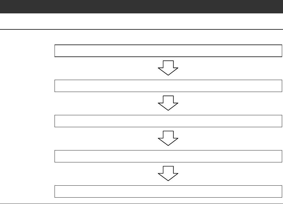
2-2. Executing Conditioning
Operation flow
The procedure for executing conditioning consists of the following steps.
2-2-1 Replacing the chuck table
2-2-2 Verifying FRANGE DRESSING screen data
2-2-3 Executing conditioning
2-2-4 Checking the end face accuracy
2-2-5 Completion of conditioning