DFD6361-Maintenance.pdf - 第607页
F-37 1-6. Re placing the Pad of the Up per Arm Section Before replac ement Have on hand the following items for replacing. - Phillips screwdrive r Procedur es for replaci ng the pad of the uppe r arm secti on W ARNING - …

F-36
1-5-3. Completion of replacing the spray tip
Procedures for completion of replacing the spray tip
Step No. Do This
(Continued from the previous section)
1
Turn ON the facility power source.
2
Open the circuit breaker lever lockout and then turn ON the
circuit breaker.
3
Insert the key into the main switch and then turn ON the main
switch.
4
Press the <System Initial> button to effect system initialization.
F-37
1-6. Replacing the Pad of the Upper Arm Section
Before replacement
Have on hand the following items for replacing.
- Phillips screwdriver
Procedures for replacing the pad of the upper arm section
WARNING
- When you perform the procedure set forth in this section, you have
to place your hands in the X-axis and a transport drive section. If
other person touches the machine during maintenance, your fingers
or hands may be caught or cut off by inadvertently activated
machine.
Ensure that no other person touches the machine while perform
maintenance.
- If any touch panel control is inadvertently activated during
maintenance or inspection, unexpected machine operation may
cause death or serious injury.
While you don't use the touch panel, press the Disco's logo button
located at the upper left of the screen in order to lock up and
deactivate the touch panel.
Step No. Do This
1
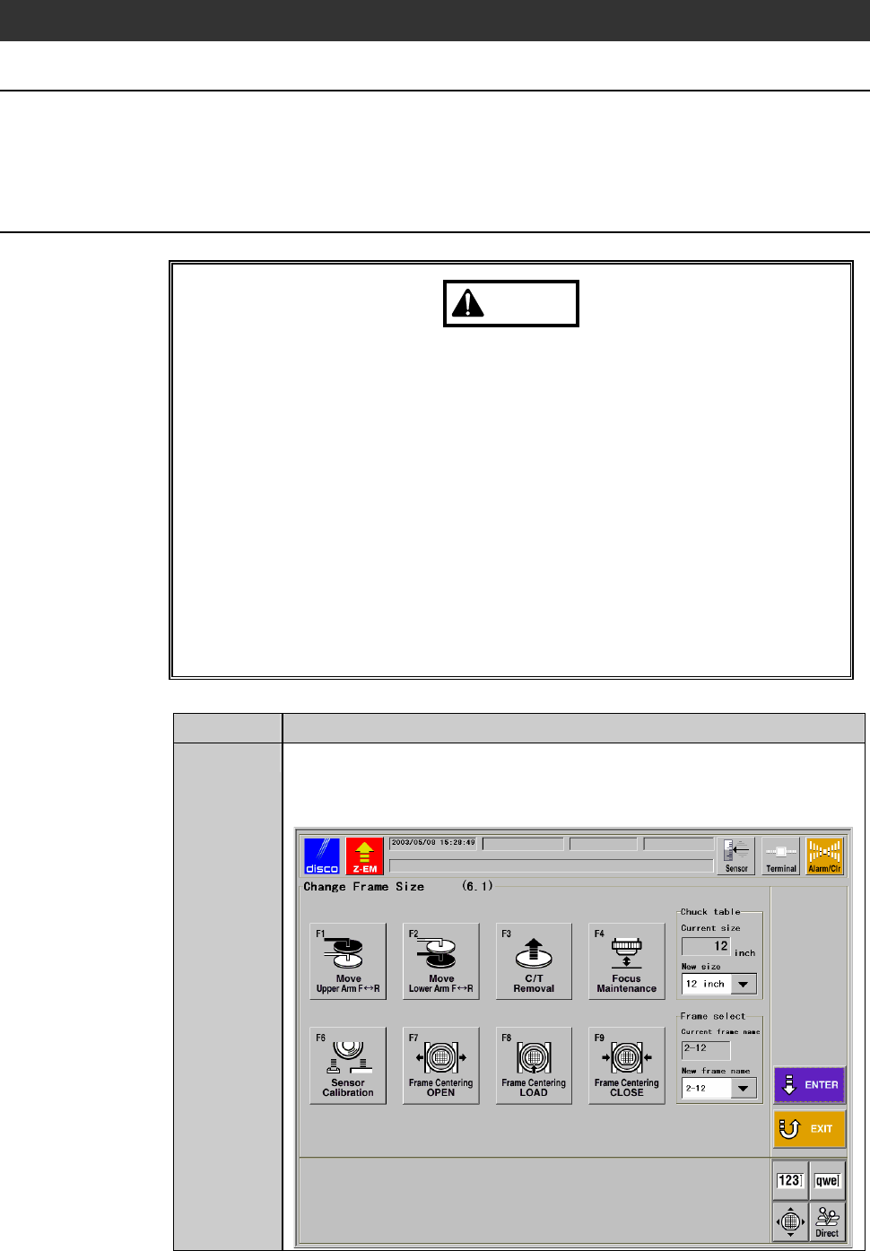
From the MACHINE MAINTENANCE screen [screen 6.0],
press the <F1> button.
- The CHANGE FRAME SIZE screen [screen 6.1] then appears.
F-38
Procedures for replacing the pad of the upper arm section (Continued)
Step No. Do This
2
From the CHANGE FRAME SIZE screen [screen 6.1], press the
<F1> button.
- The upper arm moves to above the chuck table.
3
Verify that the upper arm movement is stopped completely.
4
Open the front arm section cover.
5
Remove the tube.
6
Slide the pad plate toward outside, and then remove it.
- Check the orientation of the pad late for reinstallation.
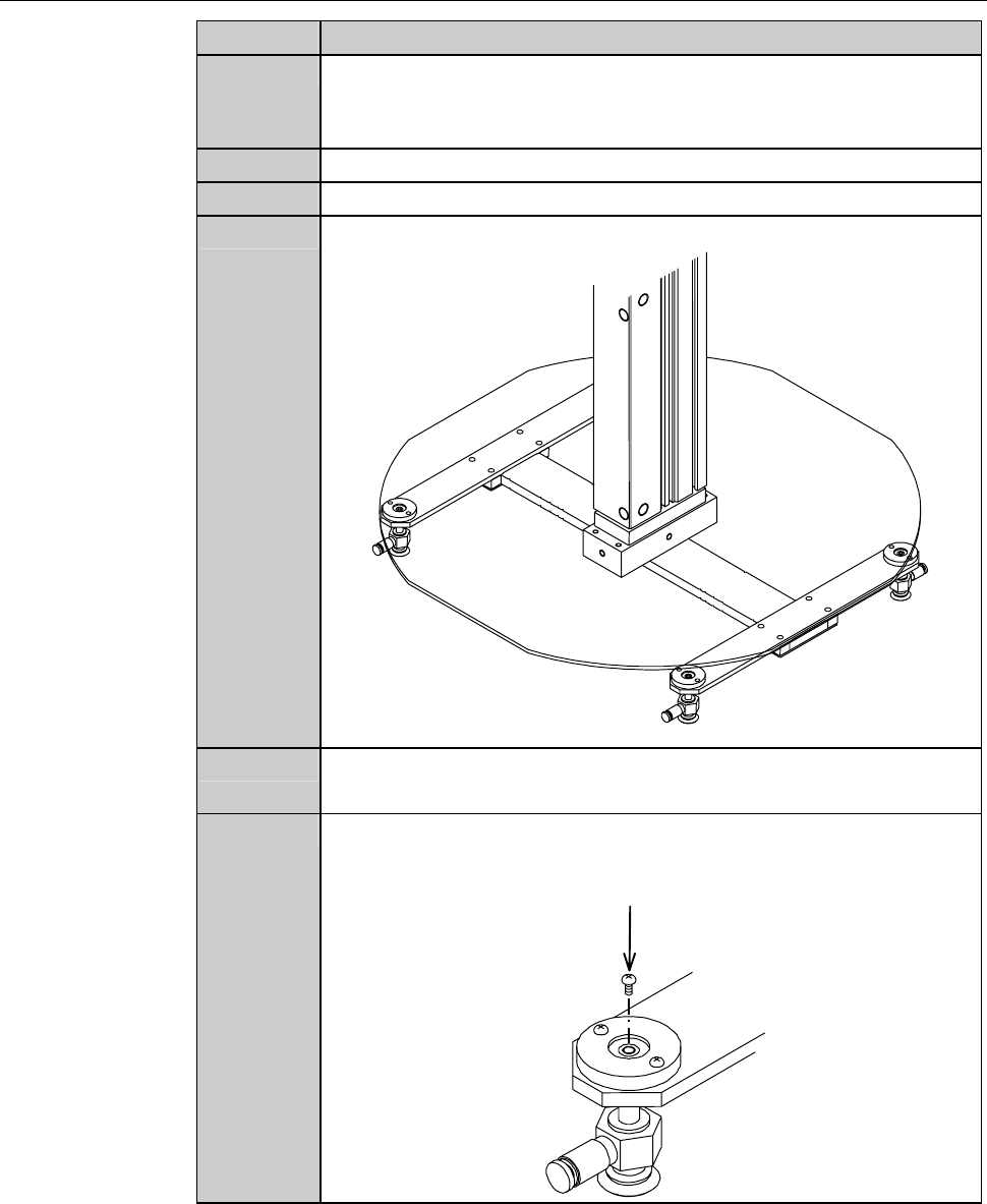
7
Remove the retaining screw of the joint.
Retaining screw
(Cross-shaped recess screw)