DFD6361-Maintenance.pdf - 第80页
B-8 Procedur es for mounti ng the c huck table ( Continued) Step No. Do This 9 Execute the setup process. - For the standard machi ne; Execute the contact setup. - For the machine incorp orated with the non-contact setup…
B-7
1-2. Mounting the chuck table
Procedures for mounting the chuck table
Step No. Do This
(Continued from the previous section)
1
With a lint-free cloth moistened with alcohol, clean the chuck
table to be installed and the table base.
2
Check the position of the notch on the side of the chuck table.
3
Set the chuck table on the table base so that the notch points the
front of the machine.
- When the chuck table is properly placed, the protrusion of the
chuck table backside mates with the hole of the table base.
4
Press the <Close> button to release lock of the touch panel.
5
Turn ON the vacuum system by pressing the <F3> button to
secure the chuck table.
6
Close the front arm section cover.
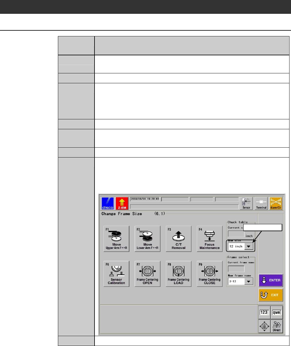
7
Enter the size of the installed chuck table in C/T (chuck table
size) column of CHANGE FRAME SIZE screen [screen 6.1].
- In the example screen shown below, 12-inch chuck table is
used.
ÿ
Select data here
G0102 PressENTERtowritedata.
8
2-8-1
8
Press the <ENTER> button to finalize the data.
B-8
Procedures for mounting the chuck table (Continued)
Step No. Do This
9
Execute the setup process.
- For the standard machine; Execute the contact setup.
- For the machine incorporated with the non-contact setup
[optional accessory]; Execute the sensor calibration setup.
- About setup;
See the section B-7, [Setup] of the Operation Manual.
10
Execute the focus maintenance.
- About focus maintenance;
See the section B-6-5 of the Data Maintenance Manual.
11
Press the <System Initial> button to effect system initialization.

B-9
2. Flange/Hub Mount Replacement
Summary of this section
This section describes the replacement procedure of the flange or hub mount.
If you use a flange type blade, see the section 2-1, [Flange Replacement], and
go to the section 2-2, [Hub Mount Replacement] for a hub type blade.
Section No. Title Contents
2-1 Flange Replacement
(1.2 kW Spindle)
- Flange replacement procedure
(forwasherblade)
2-2 Hub Mount Replacement
(1.2 kW Spindle)
- Hub mount replacement
procedure (for hub blade)
2-3 Flange Replacement
(1.8 kW Spindle)
[Optional Accessory]
- Hub mount replacement
procedure (for washer blade)
2-4 Hub Mount Replacement
(1.8 kW Spindle)
[Optional Accessory]
- Hub mount replacement
procedure (for hub blade)
2-5 Flange Replacement
(2.2 kW Spindle)
[Optional Accessory]
- Hub mount replacement
procedure (for washer blade)
2-6 Hub Mount Replacement
(2.2 kW Spindle)
[Optional Accessory]
- Hub mount replacement
procedure (for hub blade)