DFD6361-Maintenance.pdf - 第24页
A-8 Summary of this sectio n (Continued) Section No. Ti tle Conte nts 2-8 Pre-alignment Section - Component name of the pre- alignme nt section - Mechanism of t he pre-a lignment section 2-9 Transport Section - Component…

A-7
2. Axis Section
Summary of this section
This section describes the structure and function of each axis.
Section No. Title Contents
2-1 Axis Arrangement - Axis arrangement of the machine
2-2 X-axis Section - Component name of the X-axis
section
- Drive section mechanism of the X-
axis section
- Axis position detection sensor of the
X-axis section
2-3 Y (Y1 and Y2)-axis
Section
- Component name of the Y (Y1 and
Y2)-axis section
- Drive section mechanism of the Y
(Y1 and Y2)-axis section
- Axis position detection sensor of the
Y (Y1 and Y2)-axis section
2-4 Z (Z1 and Z2)-axis
Section
- Component name of the Z (Z1 and
Z2)-axis section
- Drive section mechanism of the Z
(Z1 and Z2)-axis section
- Axis position detection sensor of the
Z (Z1 and Z2)-axis section
2-5
θ -axis Section
- Component name of the θ axis
section
- Drive section mechanism of the
θ-axis section
- Axis position detection sensor of the
θ-axis section
2-6 Spinner Section - Component name of the spinner
section
- Mechanism of the spinner section
2-7 Elevator Section - Component name of the elevator
section
- Drive section mechanism of the
elevator section
- Cassette setting position
- Inspection cassette setting position
- Components of UV irradiation unit

A-8
Summary of this section (Continued)
Section No. Title Contents
2-8 Pre-alignment Section - Component name of the pre-
alignment section
- Mechanism of the pre-alignment
section
2-9 Transport Section - Component name of the transport
section
- Mechanism of the transport section
2-10 Microscope Section - Component name of the microscope
section
- Mechanism of the microscope section
2-11 Spindle-axis Section - Component name of the spindle-axis
section
- Mechanism of the spindle-axis
section
- Piping of the spindle-axis section
- Blade mounting to the spindle section
A-9
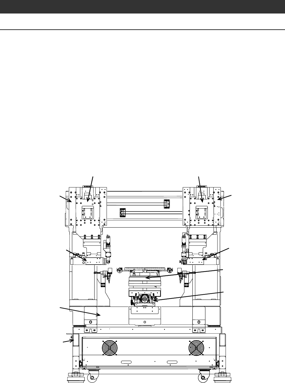
2-1. Axis Arrangement
Axis arrangement
As shown below, the machine consists of the X-axis section, Y (Y1 and Y2)-
axis section, Z (Z1 and Z2)-axis section, θ-axis section, spindle (spindle1 and
spindle2)-axis section, spinner section, elevator section, lower arm section,
upper arm section, push-pull arm section, frame centering section, main body
base, electrical system section and main body frame.
- The X-axis consists of the highly straight linear guide, ball-bearing
leadscrew section and θ-axis section located on the leadscrew section. Being
accurately positioned at right angles to the Y-axis, the X-axis moves to the
right and left.
- The Y (Y1 and Y2)-axis mainly consists of the indexing mechanism and
moves forward and rearward.
- The Z (Z1 and Z2)-axis mainly consists of the spindle and its vertical
movement mechanism.
Z1-axis section
Y1-axis section
Z2-axis section
Y2-axis section
Main body frame
Spindle2-axis section
X-axis section
θ-axis section
Main body base
Spindle1-axis section