DFD6361-Maintenance.pdf - 第664页
F-94 4-1-2. Re placing t he flowmete r Procedur es for replaci ng the flowmeter CAUTION The brack et contai ns pipes for the flow meter and sw itch harnesses . In the re moval of the br acket, exercise car e not to pul l…
F-93
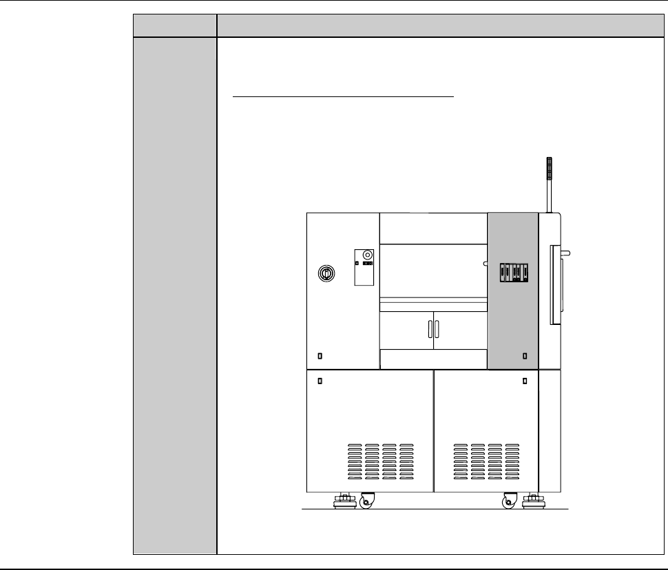
Procedures for removing the machine outer cover (Continued)
Step No. Do This
5
Remove the cover [U]. Then store it sufficiently away from the
working area.
- For the cover removal procedure;
See the section B-2-2, [Removing the Machine Outer Cover,
Monitor and Status Indicator] of Installation Manual.
ÿ
[U]
LEFT SIDE
Continued in the next section.
F-94
4-1-2. Replacing the flowmeter
Procedures for replacing the flowmeter
CAUTION
The bracket contains pipes for the flowmeter and switch harnesses.
In the removal of the bracket, exercise care not to pull it strongly with
undue force.
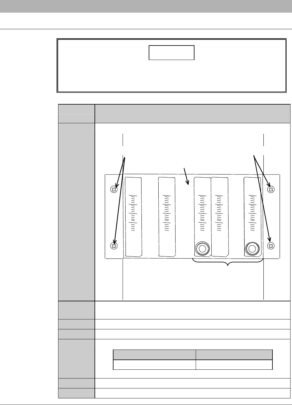
Step No. Do This
(Continued from the previous section)
1
Unscrew the retaining screws of the bracket.
Retaining screws Retaining screws
Bracket
Flowmeter
2
Remove the bracket slowly, being careful not to unplug the
junctions at the backside of the bracket.
3
Disconnect the piping and joints of the flowmeter..
4
Remove the flowmeter.
5
Mount the new flowmeter to the bracket.
Part Name Part No.
Flowmeter MOHEH056--C
6
Connect the removed piping to the new flowmeter.
7
Reinstall the bracket in its original position.
Continued in the next section.
F-95
4-1-3. Completion of replacing the flowmeter
Procedures for completion of replacing the flowmeter
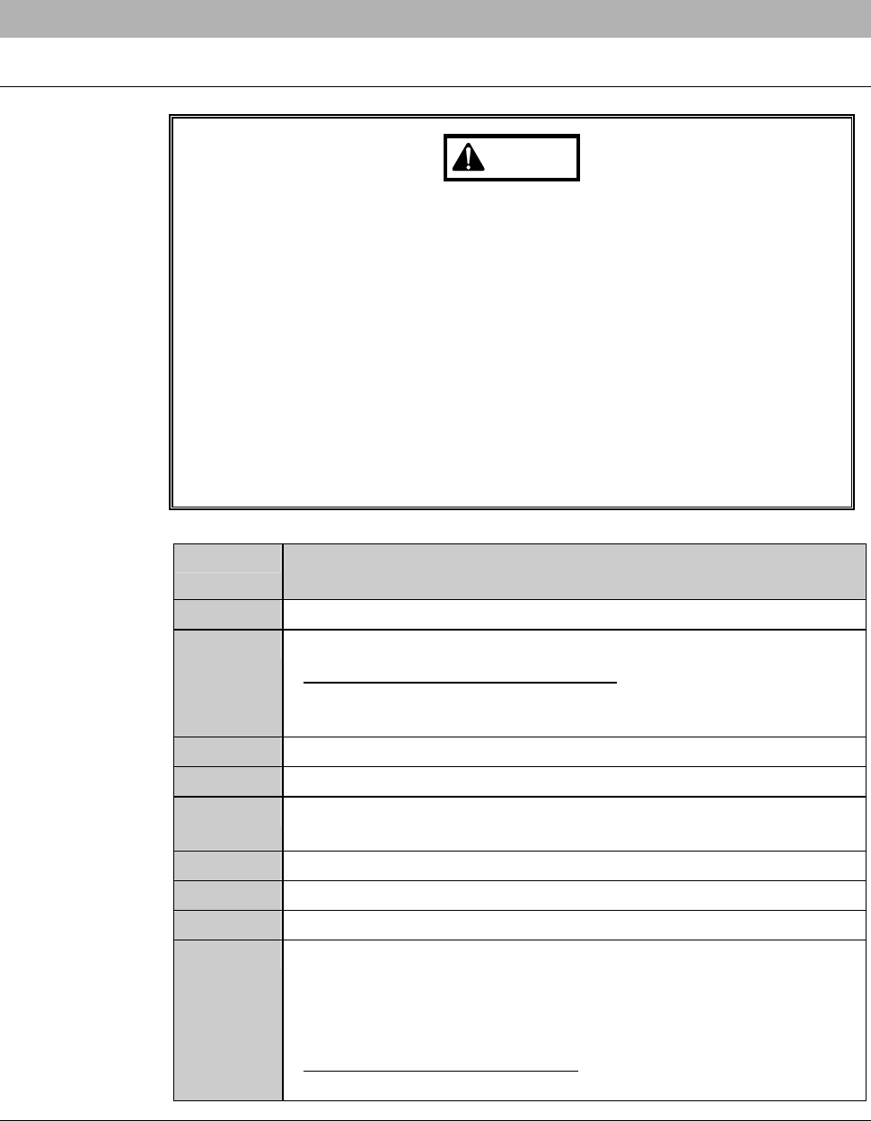
WARNING
- If you operate the machine while the machine interior or floor is wet
with water, you may receive electric shock that could result in
serious injury or death.
If the machine or floor is wet with water, do not turn ON the facility
power source until it dries.
- Upon the completion of flowmeter replacement, turn ON the wheel
coolant system to make sure that no water leakage occurs. If you
operate the machine while the machine interior or floor is wet with
water, you may receive electric shock that could result in serious
injury or death.
If any water leakage is found, shut off the facility power supply and
then properly install the piping again.
Step No. Do This
(Continued from the previous section)
1
Make sure that there is no water leakage inside the machine.
2
Reinstall the cover [U] in its original position.
- For the cover installation procedure;
See the section B-1-6, [Mounting Machine Outer Covers] of
Installation Manual.
3
Open the facility main valve of the wheel coolant water.
4
Turn ON the facility power source.
5
Open the circuit breaker lever lockout and turn ON the circuit
breaker.
6
Insert the key into the main switch and turn ON the main switch.
7
Press the <System Initial> button to effect system initialization.
8
Adjust the flow rate.
9
Start the machine and conduct dummy cutting for more than 30
minutes.
- Make sure that no water leakage occurs from the flowmeter
piping joint.
- When the water leakage occurs;
Repeat the steps 4-1-1 through 4-1-3 of this chapter.