DFD6361-Maintenance.pdf - 第596页
F-26 Procedur es for re placing the c arbon brus h assembl y (C ontinued) Step No. Do This 3 Install the new carbon brush assembly together with the cab le to the original position. - Be caref ul so that the terminals of…
F-25
1-4-3. Replacing the carbon brush assembly
Procedures for replacing the carbon brush assembly
NOTICE
If the terminals of the right and left cords contact with each other, the
machine fails to detect abnormality of spindle.
Mount the right and left carbon brush assemblies so that the
terminals of their cords do not contact with each other.
Step No. Do This
(Continued from the previous section.)
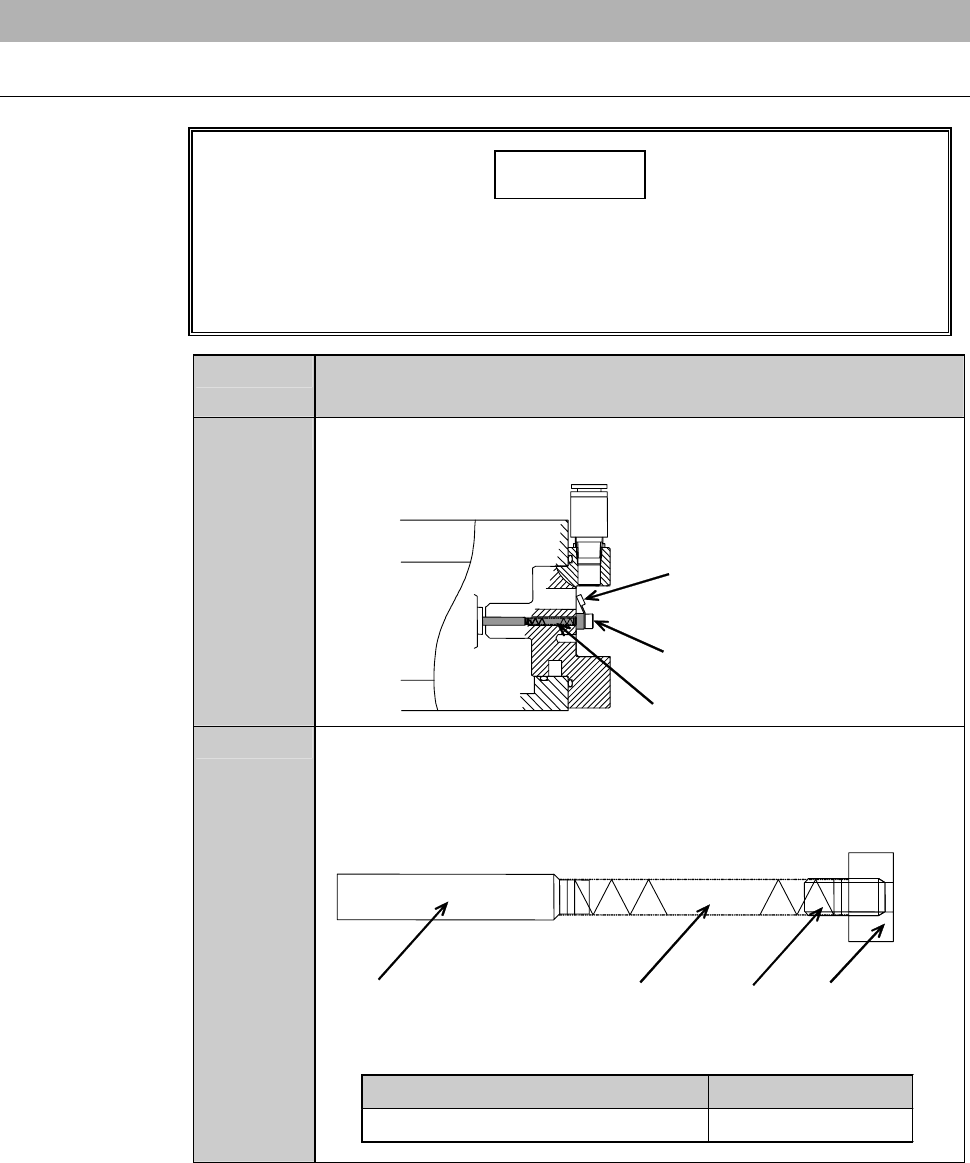
1
Disconnect the cables and retaining screw of the carbon brush
assembly.
ÿ
Carbon brush assembly
Retainin
g
screw of carbon
brush assembly
Cable
2
Take out the carbon brush assembly.
- The figure below shows the construction of the carbon brush
assembly.
- Take care not to stretch or bend the spring section.
ÿ
Carbon brush
Spring
Retaining
screw
Plate for carbon
brush
Part Name Part No.
Carbon brush assembly NCBA0015
F-26
Procedures for replacing the carbon brush assembly (Continued)
Step No. Do This
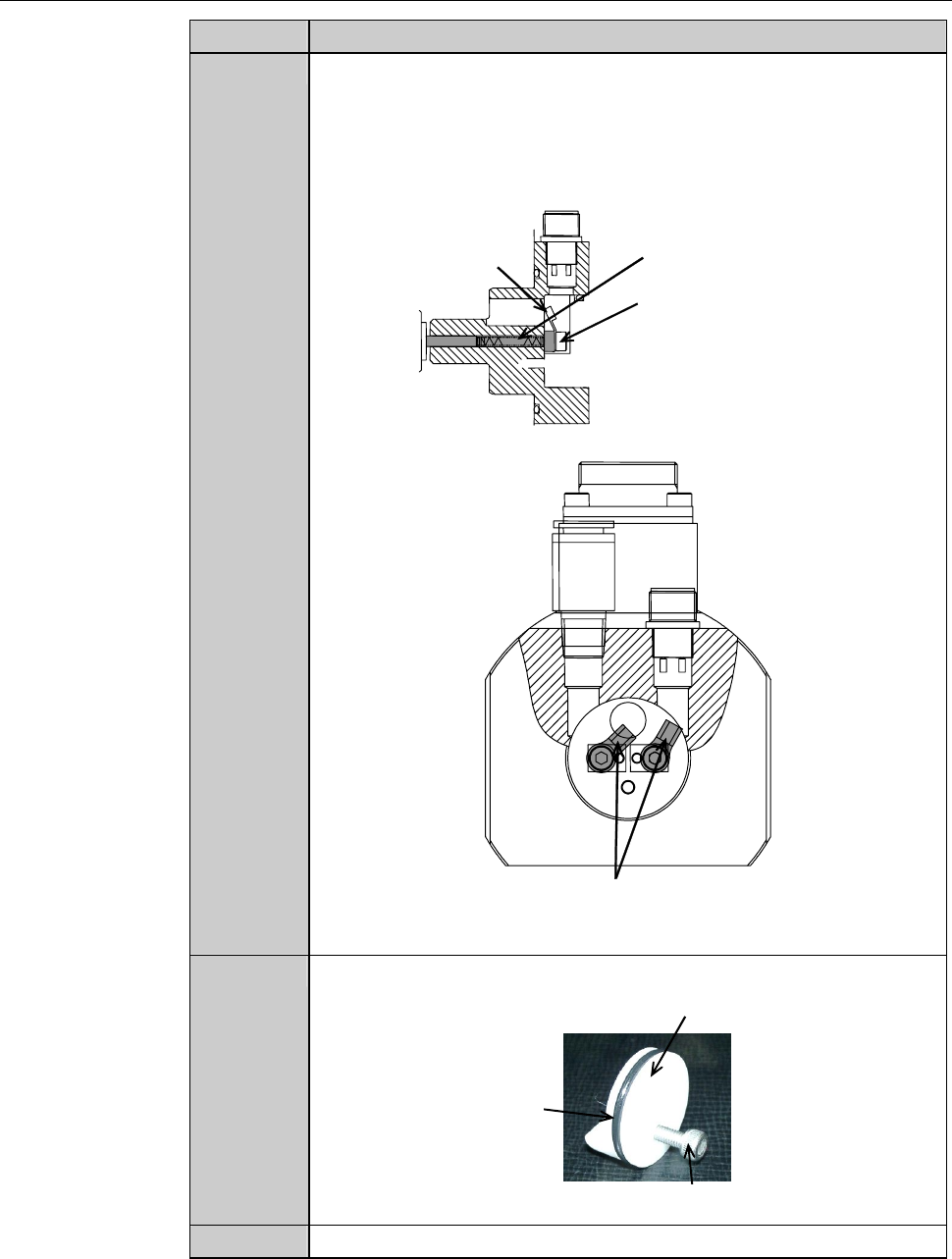
3
Install the new carbon brush assembly together with the cable to
the original position.
- Be careful so that the terminals of the left and right cable do nt
come into contact with each other.
Carbon brush assembly
Carbon brush assembly
mounting screw
Cable
[Cross-sectional view]
ÿ
Be careful so that the terminals
of the right and left cords do not
contact with each other.
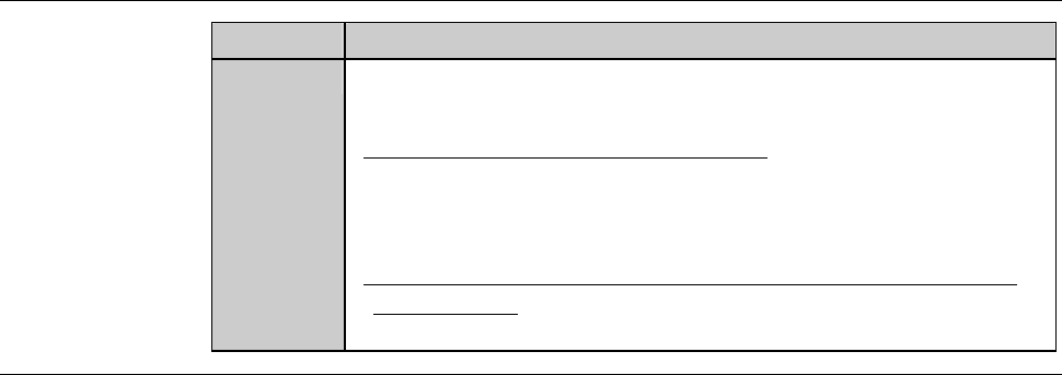
4
Make sure that the waterproof cap has an O-ring.
Waterproof cap
O-ring
M4 × 20 bolt
5
Reinstall the waterproof cap to the original position.
F-27
Procedures for replacing the spindle carbon brush assembly (Continued)
Step No. Do This
6
With the JSUSP connector unhooked, check the resistance
between the carbon brushes is lower than 20 Ω, with the tester.
-When the resistance is 20 Ω or higher;
It is possible that the contact between the spindle axis and
carbon brush is poor.
In this case, repeat the operations of the step 1 through 5.
-When the resistance remains at 20 Ω or higher after repeating
the operation;
Contact your nearest Disco Service Office.
Continued in the next section.